fireback
Newbie
Hello i have this question and was wondering if someone could help me,
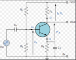
Lets say we are given a simple CE amplifier(with voltage divider on base and Rc, Re resistances)
If we are given Ic=3mA , Vcc=20V , β=100, Rth=10kΩ, Vce=10V, how can we calculate the values for R1 and R2?
Also, how can we calculate them if we are not givven the equivalent Rth value?
Thank you in advance.
(Rc instead of RL)