D.A.(Tony)Stewart
Advanced Member level 7
- Joined
- Sep 26, 2007
- Messages
- 9,057
- Helped
- 1,824
- Reputation
- 3,647
- Reaction score
- 2,215
- Trophy points
- 1,413
- Location
- Richmond Hill, ON, Canada
- Activity points
- 59,762
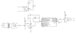
Check triac has not shorted out with an ohmmeter test on switch.