Continue to Site

Welcome to EDAboard.com

Welcome to our site! EDAboard.com is an international Electronics Discussion Forum focused on EDA software, circuits, schematics, books, theory, papers, asic, pld, 8051, DSP, Network, RF, Analog Design, PCB, Service Manuals... and a whole lot more! To participate you need to register. Registration is free. Click here to register now.

Voltage comparator for zero cross detection

Status
Not open for further replies.

jean12

Advanced Member level 2
Joined
Aug 27, 2013
Messages
529
Helped
5
Reputation
12
Reaction score
6
Trophy points
18
Activity points
5,497
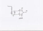
Hello,could you please advise on the circuit I may use,I realized one with operational amplifier but no succeess I thought I could get a square wave from the comparison of sine wave(12VAC/50HZ) and 12VDC but no success,check my circuit here below.

Please help I would like to use this circuit for detecting a zero cross of sine wave and then control an AC load with a TRIAC.

I will appreciate your support!!

Comparator.jpg
 
Last edited by a moderator:

Hi,

now wonder it does not work. There is no power supply. ;-)

No, seriously, the whole circuit depends on "input common mode voltage range" and this depends on supply voltage.

+++
I assume there are thousands of zero cross detection circuits around in the internet. Even in this forum there are a lot of discussions about ZCD circuits.
A simple search will answer all your questions.

Klaus
 

Failure to read specs for Vin vs V+\-

In this case V(-) input =0V therefore Vee (-) must be at least 2V below ground. BOth inputs must be biased with a DC offset between the both supply rails for this old part to work. some comparators work on a single supply or below ground, but not this one.

Consider a bias both inputs at Vout/2 for symmetrical feedback of positive feedback = 0,Vout
then AC couple the source with a cap, such that the voltage is divided down to a safe level for AC transients when no lightning surge protction is used or add a LPF for transients such as 10kHz and then use a HPF such as 1 Hz fto eliminate the DC error and minor phase shift error.
 
Last edited:

You have several mistakes:

Pin 8 is the positive supply.
Pin 4 is the negative supply. You require a negative supply because the AC waveform swings above and below ground.
Pin 1 should be grounded.
Pin 7 is the output.
Completely remove the capacitor across pins 5 and 6.

I hope you did not apply power and signals to the LM311 as shown in your circuit, because you could have damaged it.

EDIT; as Tony mentioned, a way to avoid the need for a negative supply is to offset the AC waveform to Vcc/2
 

keep in mind hysteresis only works symmetrically for noise if the bias is centred between the output swing.

A CMOS Schmitt trigger can be a simple solution if you use scale the 230Vac thru a large series R with additonal external Scottky diodes to each supply rail and a small inout cap to suppress transients. Since the AC input on a 5 V supply would be clipped to -0.2 to +5.2 and biases with large equal R to 5V,0V you can satisfy the requirements. Rather than 1% hysteresis with a large attenuated signal you actually have almost a square wave input and the Schmitt trigger logic IC adds 2V or 1/3 of Vcc of hysteresis which may be adequate and gives a logic level out. Same can be done for low voltage CMOS .
 

Dear Schmitt Trigger and SunnySkyguy,could you propose the circuit corresponding to the details you provided?What If I use LM324 or LM339 in place of LM311?

All the best!!
 

The way I would do this would be to fit back to back shottky diodes down to ground after the 30K input resistor.
That will give you a rough looking low amplitude square wave.
That can go straight into one side of your LM358, with the other input grounded.

The LM358 when run with only a positive supply voltage will work fine with input swings very slightly below ground. The shottky diodes limit the input voltage in the negative direction to something the LM358 will be quite happy with.

You can add hysteresis if you wish, but it may not be necessary.
For faster rail to rail output, consider using a single supply voltage comparator such as an LM393 with a pullup resistor on the output.
 

AC coupling to a suitable common mode voltage seems like a good idea to me. AC coupling is often ideal for zero crossing detection anyway and then you get level shifting for free.
 

Hello Warpspeed,could you provide a complete circuit using LM358 for the purpose of zero cross detection in our case?
Are you proposing that I have to replace the LM311 by LM358?Please advise

- - - Updated - - -

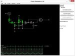
Here is the circuit ,I changed for using single supply,I am using LM339 I taken that circuit from the datasheet of LM339 but the signal I am getting is not good at all,I am using the proteus simulation for finding a good signal whith chich I may implement the circuit for ,please advise on the circuit here in attachment helping to accomplish the task.

Please help
 

Attachments

  • Forum_Comp.rar
    2 KB · Views: 114

Hi Jean,

zerocrossingdet.jpg

The LM358 is particularly good when you only have a positive dc supply voltage.
The LM311 really requires a negative supply voltage as well as positive..

I have not shown any hysteresis, it may not need it if the ac input voltage is reasonably high.

The input resistor is also open to some experimentation, but start off with perhaps 10K to 47K and see how it goes.
 

hi,
i have seen your circuit using lm339 it does not work because there is no negative voltage, if you connect your ground pin to negative voltage you will get the waveform. but in your circuit there is no negative voltage it is zero voltage ground. if you want to get an output waveform change the connection to non inverting terminal and connect inverting terminal to ground through a resistor.
remember you have to use a pull up resistor at output pin of LM339 because it is floating pin
you will get square wave pulse for only positive cycle. if you need to detect zero cross this is not the correct method and in simulation you can connect AC neutral to ground but in practical you cannot connect AC neutral to ground
 

Dear raeshkatkuri,could you please help me and give me the schematics of the circuit you judge working,I have been working on this for controlling an AC load with microcontroller but an AC Voltage controller is difficult for me to be implemented,I have chosen LM339 for using single supply(+VCC and Ground),if you can better provide to me the circuit which can detect the zero cross using LM324,LM339,or LM311 those are the ICs I can find on my disposal easily.

Please help,

Thanks

- - - Updated - - -

Dear raeshkatkuri,could you please help me and give me the schematics of the circuit you judge working,I have been working on this for controlling an AC load with microcontroller but an AC Voltage controller is difficult for me to be implemented,I have chosen LM339 for using single supply(+VCC and Ground),if you can better provide to me the circuit which can detect the zero cross using LM324,LM339,or LM311 those are the ICs I can find on my disposal easily.

Please help,

Thanks
 

oBEFORE you think of designing ANYTHING, start with a spec.
Define all inputs, measurments,,control conditions and outputs.

This includes signals and power. Think Hierarchical Input Processes, Outputs HIPO.

So far it seems you want to control some load and have an AC logic clock, perhaps measure peak AC levels or some brown out conditon. Power supplies tend to have a hold up time at 230Vac nom for 2 cycles after a dropout, and less if below nom. and more if less that rated load.

Be specific, about what you need, what you know and don't know.

Use point form like a datasheet spec.
 
Last edited:

ok am ready to help you but i need some specifications

what is your AC voltage input?
why you are going for zero cross detection?
what type of switch you are using to switch on the AC load? (TRAIC or Relay) what is there part number
what is your maximum AC load (power)?

provide me this details i will give you complete schematic
 

Hello rakeshkatkuri, the specifications you require are the following:

the AC voltage is 12V,after a transformer the max input is 220V
I am referring to zero cross detection for firing a TRIAC which controls an AC load +a potentiometer(variable resistor) for increasing or decreasing the firing angle
for switching on the ac load I am using a TRIAC a BTA26-600
The maximum power of the AC load is 2KW
the codes in programming using ccs c compiler or microc or assembly I have to read the AN0 potentiometer and then through the variation of this potentiometer the firing angle is adjusted so that the power delivered to the load may be variable using the potentiometer.

Give me a day time
 

    V

    Points: 2
    Helpful Answer Positive Rating
A simple 50us ZCS pulse cct.
Diodes are internal to CMOS input. AC input R's are axial HV rated. (>+500V) string more in series for safety of parts in case of 3kV

Simulation https://goo.gl/Srqv9M
ZCS.jpg

This design clips the 640Vpp to 5.2,-0.2 V with 320uA to the ESD diodes. This could all be done is PIC firmware too, or all done in hardware, with no transformer.
 
Will the above circuit be immediately applied on the RBO pin of the PIC?If yes,will this Tahmid blog help or be enoug hwith the codes?

Regards
 

I come out by obtianing a simple operating ZC circuit https://microcontrollerslab.com/zero-crossing-detector-circuit-using-pic-microcontroller/ and I used the same codes as those on this posted link but no success,the voltage on the load remain the same.
>>How could a variable be used in delay() funnstion,I ask this for meaning in case I am using a potentiometer for adjusting the voltage,how the value_ADC could be inserted in the delay() function?

Please help
 

A simple 50us ZCS pulse cct.
Diodes are internal to CMOS input. AC input R's are axial HV rated. (>+500V) string more in series for safety of parts in case of 3kV

Simulation https://goo.gl/Srqv9M
View attachment 130452

This design clips the 640Vpp to 5.2,-0.2 V with 320uA to the ESD diodes. This could all be done is PIC firmware too, or all done in hardware, with no transformer.

Hello,here is my circuit,definitely I found a circuit helping to detect the zero cross as I posted the link but the bulb is lighting at maximum,no change and not depending to the delay(firing angle)I provided,what can I do??
 

Attachments

  • Forum_OKK.zip
    25.8 KB · Views: 101
Status
Not open for further replies.

Similar threads

Part and Inventory Search

Welcome to EDABoard.com

Sponsor

Back
Top