Continue to Site

Welcome to EDAboard.com

Welcome to our site! EDAboard.com is an international Electronics Discussion Forum focused on EDA software, circuits, schematics, books, theory, papers, asic, pld, 8051, DSP, Network, RF, Analog Design, PCB, Service Manuals... and a whole lot more! To participate you need to register. Registration is free. Click here to register now.

[SOLVED] vmod tft interface with virtex-5

Status
Not open for further replies.

Robin Khosla

Member level 4
Joined
Aug 2, 2012
Messages
76
Helped
7
Reputation
14
Reaction score
6
Trophy points
1,298
Activity points
1,861
i want to interface a VMOD TFT with virtex-5

VMOD TFT can be operated as both a TOUCHSCREEN and as an display device.. i only want to use it as a display. problem i am facing is that, it is showing only white colour even by changing the RGB pattern..
can anyone help me regarding it... Some documents regarding it will also be helpful...

the documents available with this module are attached here...
 

Attachments

  • VmodTFT_rm.pdf
    457.7 KB · Views: 68
  • Genesys_rm.pdf
    2 MB · Views: 90

What's the design you're using? Something you've written yourself, or have you converted the Atlys/Nexys 3 demo project?

Are you sure the UCF is correct? Does your simulation show that you're sending the correct signals to the display?
 

no i have not converted the project actually some of the libraries are missing...
such as digilent.video
so i am unable to synthesis the code

i am currently working on only using that as a display device...
the signal are working fine as per figure1 and figure2 in VMODTFT_rm.pdf
 

Attachments

  • VmodTFT_rm.pdf
    457.7 KB · Views: 76

You haven't given us a lot to go on. How do you know that the signals are 'working fine'? Obviously something is not right if the display isn't working.

Here are the things I would check:

- Is your design's timing properly constrained? For both the system clock and the module's setup and hold time constraints? Is it actually meeting the timing constraints?
- Does the simulation waveform match the specifications for the module exactly? Are you following the power on sequence correctly?
- Have you constrained signals to the correct pins? Have you double checked this? With a logic analyser or an oscilloscope?
- The datasheet provided by Digilent is pretty sparse. Have you simulated the Atlys design to see what its signals look like? I'm not sure why you would have missing libraries, but it's been a while since I looked at the code.. try contacting Digilent for help.
- Is your output logic 3.3V as required by the module?
 

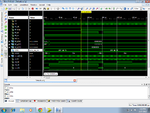
these are the simulations for the first 3states
clk = 100 MHz
clk_9 = 9 MHz
clk_50= 25 Khz

tft_disp, tft_de, tft_en, led_en are assigned value as per the figure1 of vmod_tft


pwrup.png


The thing is that when led_en is given '1' (suppose in rst state )then the back-light glows and shows white irrespective of whatever data i give at RGB...
but when i give led_en an clk of 25Khz as mentioned in data sheet in data transmit stage then even the back-light doesn't glows
 

the problem solved
actually just after the transmit stage i was sending the power down stage
so after initializing the lcd we need to stay in transmit stage
rest everything is correct i made it run
see the video below:
https://www.youtube.com/watch?v=wfOOsut469Y
 

Status
Not open for further replies.

Part and Inventory Search

Welcome to EDABoard.com

Sponsor

Back
Top