Continue to Site

Welcome to EDAboard.com

Welcome to our site! EDAboard.com is an international Electronics Discussion Forum focused on EDA software, circuits, schematics, books, theory, papers, asic, pld, 8051, DSP, Network, RF, Analog Design, PCB, Service Manuals... and a whole lot more! To participate you need to register. Registration is free. Click here to register now.

Variations in phase margin

Status
Not open for further replies.

vinayakdabholkar

Advanced Member level 4
Joined
Nov 29, 2009
Messages
114
Helped
0
Reputation
0
Reaction score
0
Trophy points
1,296
Location
goa
Activity points
2,195
Hello
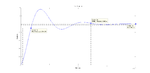
I designed a type III compensator based on a excel sheet provided by sipex. I then plotted the closed loop bode plot for my entire system.
What i saw is that as i change the position of the first zero of the compensator the phase margin changes, but not linearly.As i place the first zero closer and closer to the double pole frequency Flc the phase margin should have reduced but for some values it increases while for some it decreases.
For different zero scale factors i.e percentage of double pole frequency where the first zero is being placed i get these phase margins
zsf -- Phase margin
0.1(10%) -- 36.2
0.3 -- 36.6
0.6 -- 36.3
0.9 -- 36.1
1.0 -- 36.3
1.1 -- 36
1.2 -- 36.1
1.5(150% of Flc) -- 35.7
I expected it to decrease linearly and for the system to become unstable. The output of the buck converter becomes unstable for a zsf of 1.5 with a load step.
Is this the expected behaviour ?
I have attached the matlab file i used to get the bode plots
 

Attachments

  • latest outputs.rar
    575.9 KB · Views: 53

Phase margin reduction with load current is presented by the related property of overshoot and ringing. The ESR of the output Cap cannot be too low in some cases and the load current sometimes needs a 1~10% minimum for good performance. THis is normal.
 
Could someone provide some help to make this system stable
I have attached the bode plot of the closed loop system. I have also attached the matlab script i used to generate the bode plots along with the transfer functions used for the same ?
What changes should i go for ? bandwidth/ Compensator components ?

- - - Updated - - -

I tried changing the bandwidth but still no success. The transfer function that i want to stabilize is the closed loop current transfer function Giic(s)
 

Attachments

  • latest outputs.rar
    62.3 KB · Views: 44

First of all, when you change a zero frequency, you should also see the magnitude of the loop response change, not just phase, which will also change fc. Are you taking this into account? Or are you simultaneously modifying some other parameter (like K) to keep fc constant?

To do your analysis, I would recommend forgetting about the circuit component equations for now and just directly define the pole and zero frequencies and K of your system. That's a lot more straightforward than modifying component values trying to recreate the same effect. Once you have pole/zero values you like, then you can derive component values for them.
 

Does this system require any kind of controller ? As there is no steady state error and also the rise time is considerably fast.
This is the step response of the output filter of a buck converter
 

Attachments

  • withparameters.png
    withparameters.png
    10 KB · Views: 66

Is this tuning i am trying to do correct. To the response of post #5 i tried to tune it.
When i increase kp i see improvements in rise time and settling time while i get a steady state error. I tried increasing kp further and the output never starts to oscillate.
when i introduced Ki the steady state error went but the rise time and settling time worsened(from microsecond range the became in seconds)
please help me out here
 

Attachments

  • tuning.rar
    7.1 KB · Views: 51

Status
Not open for further replies.

Part and Inventory Search

Welcome to EDABoard.com

Sponsor

Back
Top