Continue to Site

Welcome to EDAboard.com

Welcome to our site! EDAboard.com is an international Electronics Discussion Forum focused on EDA software, circuits, schematics, books, theory, papers, asic, pld, 8051, DSP, Network, RF, Analog Design, PCB, Service Manuals... and a whole lot more! To participate you need to register. Registration is free. Click here to register now.

Variable frequency sinusoidal wave oscillator

Status
Not open for further replies.
You're thinking this is a simple little circuit with a simple answer. It is not. For starters, output of +/- 15V can't be achieved with an LM118 . Best you can do is maybe 10V at 2 MHz with feedforward comp and that raises stability issues. You'll get at least several percent distortion with a simple circuit. The opamp alone can maybe drive a 1K resistive load. You'll need leveling. You need a driver. To get that whole range without range-switching is near impossible. Do some more research on function generators. There are plenty of circuits on the net. None are something you can do with 2 ICs. Revise your requirements to make it into a simple task or be prepared to do a significant amount of work.
 
but at frequencies more than 1.3MHZ i can not use my integrator , because the out put shape will destroy . and i think that my op amp can not work at that frequencies ( its harmonics ) . i used LM118 . what should i do ?

It's all in the LM118 datasheet. As Robert explained, LM118 can work with higher large signal bandwidth using feedforward compensation. You're nevertheless very near to the devices absolute speed limits. I wonder, if using a more recent high speed OP would be reasonable.
 
The OP is Iran. Likely difficult access to better parts. The 'simple' circuit is a Wien bridge in 4 ranges, FET leveling, Class A discrete cascode buffer. +/-15V on the osc, +/-25 or 30 on the buffer. Maybe 0.1% distortion. Half dozen 318s. Another one if you need single-pot adjustment, some FETS or an LDR if you want VCO capability but worse distortion. Schematic is left as an exercise for the student.
 
Dear FvM
Hi
What do you mean by feedforward compensation ? is you mean , that if i do that , i can use from lm118 for this aim? if yes , how can i do that ?
And is it possible , that you introduce some high speed op amps to me , please?:roll:
Regards
Goldsmith

---------- Post added at 23:56 ---------- Previous post was at 23:49 ----------

Dear Mr Robert Hoffman
Hi.
I'm very happy , that you joined in EDA board.
I read in one book , that the wien bridge oscillator can not oscillate at high frequencies. is it right?
and what do you mean by "4 range fet leveling Class A discrete cascode buffer. +/-15V on the osc, +/-25 or 30 on the buffer"? is your mean that , it is possible to obtain +-30 volt with that? and if yes , what is that accurately? is it possible that you guide me , that how can i design that , please?
And what do you mean by :'Half dozen 318s"?
Is it possible that you guide me , please?:cry:
Thanks in advance
Best Regards
Goldsmith
 
Last edited:

I used a 2206 in my waveform generator. Its frequency changes slightly with supply voltage. It needs tight regulation. (This is probably the case with other sinewave generators as well.)

It is best to use several frequency ranges. I wanted my generator to provide 1Hz to 300 kHz. My junk box had a four-position rotary switch. So I used that.

Turning the switch to each of the four positions connects a different capacitor to the 2206. The IC is very easy to use in this regard.

I had to test many capacitors to find four values which generate the sweep ranges I wanted.

The pot sweeps a ratio of 1:30. Even then I have trouble positioning the pot to get the exact frequency I want. To try to do the entire 1Hz to 2MHz in a single sweep will not work for you.

The 2206 has two glitchy spots at the crest and trough of its sinewave. It also needs to have its sinewave adjusted to minimize distortion. To my ears it sounds like a clean waveform.
 
You'll find the details about how to apply feedforward compensation in the full LM118 datasheet.
High speed OP - depends on what's available at your place.

The Function generator circuit I previously posted isn't using any high speed ICs except for a line receiver utilized as comparator, and a larger amount of discrete transistors.
 
Sorry I can't give you a graduate education in circuit design. Once you spend 30 years designing circuits you'll catch on. Do some Google searches on the terms you're interested in. It will take you about a week. The 318 datasheet tells you how to do feedforward comp. It's faster. It also overshoots and gives stability problems. Search the sites for TI and Linear Technology and Maxim and National. You'll find plenty of fast amps. Whether you can get them or afford them or use them, that's another story. The 318 is ancient. Many of the new fast ones are low voltage, not +/-15. Many are only in small surface mount or BGA. Can't breadboard with them easily. You can get whatever swing you want on the output with enough power. ICs only go so far. When you want some things you have to use actual transistors. A Wien Bridge osc is pretty low distortion and will certainly work up to a couple MHz. State variable is another option. National has several good app notes. They both need leveling loops. Neither will do your whole range in one shot. About 1000:1 in one range is as good as you get. You got a lot of good hints here. Nobody is going to do your design for you. Go read a couple thousand pages and ask more questions when you understand everything that all the people here have suggested. You won't do this with two integrated circuits. It won't take 20 but it will probably take at least 6. It can be done with 118/318 opamps. It's at the limit of their range but possible.
 
  • Like
Reactions: FvM

    FvM

    Points: 2
    Helpful Answer Positive Rating
Dear BradtheRad
Hi
Thank you for your reply.
do you think that it is possible to obtain 2MHZ from XR2206?
by the way i want to design the circuit without the direct generators such as xr2206 . is it possible that you guide me to design that circuit , please?
Appreciate
Goldsmith

---------- Post added at 01:08 ---------- Previous post was at 00:41 ----------

Dear FvM
Is it possible , that you More describe the circuit the you posted , please?
And in your idea , is it good choice , to design a sine generator at high amplitudes with vacuum tubes ?
Thanks in advance

---------- Post added at 01:16 ---------- Previous post was at 01:08 ----------

Dear Mr Robert Hoffman
I tested wien bride oscillator with lm318 some minutes ago , and you're right . i obtained 3.6 MHZ with lm318 . but it is a problem here. it's amplitude changed with frequency variation . and at some frequencies , it's wave form was , an square wave , and when i changed the value of rf , that improved.
How can i improve it as , that will not need the changing the rf ?
Thanks in advance
Goldsmith
 

The generator core is a triangle generator comprised of programmable current sources, a buffer, a two-level comparator and selectable capacitors.

 
Although it may be possible to make a sinewave oscillator that puts out 30 V peak to peak (not that I have ever done so)...

I have a hunch you'll often reduce it to a few volts to stay within safe operating limits of the devices you use. I have ruined more than one device when I was careless and exposed devices to overvoltage/overcurrent.

So it makes better sense (I think) to make an oscillator that puts out under 10 V peak to peak, and then amplify it if you need to.

A 30V p-to-p project will need a power supply to match it. I on the other hand made my waveform generator to run on one 9V battery. It's easily portable and it takes up little room where I've used it with PA equipment, audio equipment, digital circuits, even a few radio circuits. Etc.

By the way, to get 1Hz to 2MHz operation, you'll need to construct such an amplifier (or oscillator) that surpasses the performance of every audio amplifier I've seen. Because an audio amplifier only needs flat response and low distortion up to 20 Khz or so.

It's commendable that you want to make your own. It will be an accomplishment to make a sinewave generator with variable frequency in the range you want. In addition a frequency counter is invaluable.

A frequency counter is a whole 'nother project. I installed a frequency counter in the same enclosure with the waveform generator. There was only room for 6 digits. I had to tell myself "Someday I can modify this project if I work with higher frequencies, but right now it is sufficient for my foreseeable purposes now."

do you think that it is possible to obtain 2MHZ from XR2206?
by the way i want to design the circuit without the direct generators such as xr2206 . is it possible that you guide me to design that circuit , please?

For the XR2206 some people say 1MHz, others 2MHz. Naturally you don't have to use an IC like the XR2206 or MAX038 or 8038. Here's a web article describing nine ways to generate sinewaves:
 
Dear FvM
Hi
How can i design a circuit like your suggested circuit?
and how your circuit generated a triangular wave? and why that circuit used that jfet ( q301 ) at the out put of that op amp?
Thanks in advance
Goldsmith

---------- Post added at 18:03 ---------- Previous post was at 18:00 ----------

Dear BradtheRad
Hi
consider that you want design a function generator with analog elements , what will you do at first step?
Appreciate
Goldsmith
 

[/COLOR]I tested wien bride oscillator with lm318 some minutes ago , and you're right . i obtained 3.6 MHZ with lm318 . but it is a problem here. it's amplitude changed with frequency variation . and at some frequencies , it's wave form was , an square wave , and when i changed the value of rf , that improved.
How can i improve it as , that will not need the changing the rf ?
Thanks in advance
Goldsmith[/QUOTE]

Not to be too rude, but you're in Iran and the USA is not on especially good terms with them at the moment. Would be nice to know exactly what you're doing with this circuit. Even though this is very old technology, if it's government work I'm not inclined to educate you any further. If you want just a good sine wave, use a bridge oscillator. If you need sine, square and triangle things get more difficult. A Wien bridge needs the gain adjusted automatically and precisely to have just enough gain to oscillate but not enough to begin clipping. That's done with some variety of nonlinear feedback or an automatic gain control. If you're getting a square wave, the loop gain is too high. Reduce your feedback resistor. If it won't oscillate continuously, the gain is too low. When a good automatic gain control is used, the distortion can be very low indeed. Under .001%. If you use a very simple diode limiter, the peaks get clipped a little and the distortion is not as low. You need to define the distortion you expect. Using a triangle wave to start and doing an analog sine converter with diodes gives a wider range and it's easy to get it to oscillate. The distortion is at best a few percent. An automatic gain control can be as simple as a single JFET or rather complex. The traditional circuit uses a simple light bulb or thermistor. That works well if the frequency is at least 20Hz or so. Below that, there are problems. There are many design tradeoffs. The National Semiconductor application notes give many examples.
 

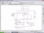
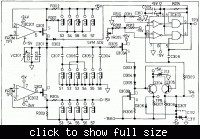
I mainly posted the circuit as an example that you can design a generator without using fast OPs. Considering that the design originates from 1985 (or may be even before), high speed OPs have been quite expensive at that time. It's not my design and I probably can't tell you for every cicruit detail why it's so. But I have designed similar circuits (at higher speed) and basically know how to.

The two OP/FET combinations on the left of the schematic are programmable current sources. There setpoint is generated on the previous circuit page, depending on the frequency and duty cycle setting. While the lower current source is permanently active, the upper can be clamped by a diode switch controlled from the 75107 comparator. So the current sources are either discharging or charging the generator capacitor. The circuit works pretty similar to the OP integrator plus comparator cicruit in the Purdue project report. But it's using a non-feedback integrator, which can typically achieve higher speeds than a feedback one, in other design up to several 100 MHz frequency and ns risetimes.
 

Dear Mr hoffman
Hi
Iran don't want to start any wars because iranians love peace. and we love the free humans(who want to think free) entire of the world.
And about the circuit . it is a simple function generator for me ( a simple student of university , that loves electronics very much).
So if it is possible , guide me please.
How can i design the AGC for the wien oscillator?
Respectfully
Goldsmith

---------- Post added at 19:39 ---------- Previous post was at 19:36 ----------

Dear FvM
Is it possible that you describe the behavior of programmable current source , please?
Respectfully
Goldsmith
 
Last edited:

consider that you want design a function generator with analog elements , what will you do at first step?

I confess that a lot of my projects began when I picked up some new IC at my local Radio Shack.

I would look over waveform generator kits at the Heathkit store. I wondered about getting the one in a big cabinet. Nice, but at greater cost than I was willing to pay.

Then I saw Radio Shack start selling the XR2206. It did a lot of things I wanted, in one package. Easy to use. Inexpensive.

I didn't yet have an oscilloscope. I didn't know how to make a sine wave oscillator that could be tuned with one pot, and would keep constant amplitude. Even now I'm not sure I could make an analog circuit that does all the XR2206 does.

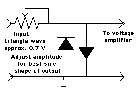
To build an adjustable sinewave generator, I'm the kind that looks for something simple and clever. I would find out what results I could get from the breakpoint design (which is similar to the method in some IC's including the 2206). Apply a triangle wave to two diodes connected in anti-parallel. As shown:

76_1326011029.gif
 
Dear BradtheRad
Hi
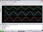
Thank you for your reply. But how this circuit change the input wave to a sine wave? with the capacitors of diodes (internal)?
and when i changed the frequency , the out put wave was not in good shape . how can i improve it? and where is the problem?
sine wave.JPG
sine wave 2.JPG
I think by changing the frequency , the out put amplitude of my integrator will change . when i changed the frequency and then the out put shape changed , but i changed the gain of my integrator , thus again the out put wave was a sine wave at good shape .
How can i improve this problem? your suggested circuit is very good if i can improve it .
Thanks in advance
Best Regards
Goldsmith
 

I think by changing the frequency , the out put amplitude of my integrator will change.
That's by design of the cicruit, the consequence of using a variable frequency square wave generator and a fixed time constant integrator instead of a self-oscillating integrator with fixed comparator hysteresis.

To improve the behaviour, refer to known variable frequency triangle generator circuits.
 
Dear FvM
Again Hi And thank you for your helpful reply .
But how can i design a fixed time constant integrator . i know all things about a simple miller integrator . but i don't know any thing about time constant integrators . is it possible that you describe it , please?
and about your last post , what are the programmable current sources ? is that a current source that with a voltage we can control it's current?
Thank you very much
Goldsmith
 

Fixed time constant (fixed RC value) integrator simply means the circuit you previously posted, complaining about varying amplitudes. A standard triangular generator like that in the Purdue project report in contrast varies the integrator time constant with a potentiometer to change the frequency without affecting the amplitude.

Even more important, it has fixed comparator thresholds that define the upper and lower level of the triangular waveform.. The same thing applies to the FG1617 generator circuit from post #29.
 
Dear FvM
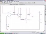
I designed this programmable current source ( for half cycle) . how can i use it as an integrator?
curren source.JPG
Regards
Goldsmith
 

Status
Not open for further replies.

Part and Inventory Search

Welcome to EDABoard.com

Sponsor

Back
Top