BusyEng
Newbie level 6
Hi all,
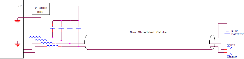
I would like to know how I can use a multi-wire cable (including battery and wires that carry audio signals) as a 2.4GHz antenna. The cable has no shielding and all wires go in parallel with each other in the cable. The cable is about one foot long, however, I can change the cable length if necessary.
I understand that I can use some small capacitors (in pF range) to inject the RF signal to the cable. However, I am not sure on how to choose the length of the cable, how to select the capacitor values, and also how to select the wire in the cable as the antenna (should I inject the RF signal to all of them?). I am also not sure how this will affect the antenna impedance seen by the RF source.
Any practical advice or sample schematic will be very helpful.
Thanks.