Continue to Site

Welcome to EDAboard.com

Welcome to our site! EDAboard.com is an international Electronics Discussion Forum focused on EDA software, circuits, schematics, books, theory, papers, asic, pld, 8051, DSP, Network, RF, Analog Design, PCB, Service Manuals... and a whole lot more! To participate you need to register. Registration is free. Click here to register now.

[SOLVED] Using N-Channel MOSFET as switch to drive a resistor load

Status
Not open for further replies.
Hi,

What gate voltage:
--> read the datasheet: R_DS_ON is specified for 4.5V and 10V.

Dissipated power:
P = I × I × R_DS_ON
0.6A × 0.6A × 0.5Ohms = 0.18W --> you may feel the increase in heat, but the Mosfet should withstand it easily when soldered to a PCB.

Try to connect the load directely to 24V supply and measure the current.

Klaus
 

Hi all

I changed to a new piece of MOSFET and managed to get it to source 0.6A to the load.

To get the MOSFET to operate as a switch, I read that it is best to operate in the linear region? Do we need to control Vds to do so?
Other than decreasing the Rds_on, is there any pros/cons to increase Vgs?
Any good application notes/information on MOSFET and using MOSFET?

Thanks for all your advice
 

Hi

I m trying to drive a resistor (dummy) load rated 24V, 0.6A using a Infineon BSP295 N-MOSFET (Attached).

A power supply is used to provide power to the circuit. A 3.3V regulator rated at 0.3A is connected to the switch then to a voltage divider before connecting to the gate. When the switch is closed, a voltage divider gives 3V to the gate. The current drawn at the initial phrase goes up to 0.6A for about 5 secs, before slowly reducing to 10mA, as if the MOSFET is not conducting. This is happening consistently.

In another implementation, the 24V is connected to the switch, a voltage divider before connecting to the gate. The voltage divider gives 13V to the gate when the switch is closed. Again, the current drawn at the initial phrase goes up to 0.6A for a longer time of about 10 secs, before slowly reducing to 10mA, as if the MOSFET is not conducting in a consistently manner.

What is wrong with my controlling of the MOSFET?
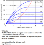


Probably the MOSFET is heating up and the conductivity is going down (even I don't know how the conductivity is going down). Check the temperature of the MOSFET
 

Added note: In this post the phrase "saturation region" is wrong. But I leave it there, because of the folowing discussion. -Klaus-

Hi,

To get the MOSFET to operate as a switch, I read that it is best to operate in the linear region?
Surely not.
You should operate the MOSFET as switch in saturation region.

If you´re in doubt (with any question), then look for reliable sources of information.
Usually wikipedia is reliable.
But in case of MOSFET operation I recommend to read some application notes from MOSFET manufacturers.
They have loads of very detailed and reliable information.

Klaus
 

You should operate the MOSFET as switch in saturation region.
Klaus, you are talking about a bipolar transistor, not a Mosfet where the linear and saturated regions are opposites.
When a Mosfet is turn on hard it is called the linear region and when it is amplifying it is called the saturated region.
Confusing, isn't it?
 

Hi,

@audioguru:
I'm referring to wikipedia:
https://en.m.wikipedia.org/wiki/MOSFET
From wikipedia:
"Saturation or active mode
When VGS > Vth and VDS ≥ ( VGS – Vth):

The switch is turned on, and a channel has been created, which allows current between the drain and source. Since the drain voltage is higher than the source voltage, the electrons spread out, and conduction is not through a narrow channel but through a broader, two- or three-dimensional current distribution extending away from the interface and deeper in the substrate....


Is this really wrong?

Klaus
 

Both Wikipedia and International Rectifier (Infineon now) show the same graphs of a Mosfet. When it is turned on hard like a switch then it is "Linear". When it is an amplifier with plenty of drain-source voltage it is "Saturated" which are the opposites to a bipolar transistor.
 

Attachments

  • Mosfet.png
    Mosfet.png
    42.5 KB · Views: 70
  • Like
Reactions: KlausST

    KlausST

    Points: 2
    Helpful Answer Positive Rating
Hi,

@audioguru.
Thanks for bringing light in the dark.
I was misinterpreting the phrases and should have thoroughly read the diagram.

@OP
Sorry for the confusion.
So the correct phrase for the operation mode of a Mosfet as a switch is "linear mode".
But that still means you should drive the gate with high voltage (much higher than V_gs_th but below it's specified absolute limit).
And you should not "regulate" this gate voltage.
--> the higher the gate voltage (correct: gate to source voltage)
* the lower is R_ds_on
* the lower is V_ds
* the lower is the dissipated power (conductive) in the Mosfet

Klaus
 

Hi

Thanks to all for the information and advice!
 

Status
Not open for further replies.

Similar threads

Part and Inventory Search

Welcome to EDABoard.com

Sponsor

Back
Top