dope40
Member level 4
Hi ,
I have recently been making a board with a usb connector and FTDI FT232RL.
The problem is that i am using a 2 layer board. I used Saturn PCB Calculator , but the traces have
to be too big .
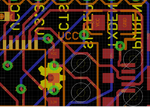
So , the conundrum is that when i saw the SparkFun USB to Serial Breakout - FT232RL https://www.sparkfun.com/products/12731, in the board file the traces are 10 mil ( 0,254 mm ) and are not side by side .

Does someone know how is this possible ?? Its my first time using usb , so my knowedge on the subject is really poor . During my reading i found a post ( Sorry cant find the link ) where i read that you can use a 18 mil ( 0.457 mm ) and a 6 mil (0.152 mm) gap .

I am also using a STF202 USB Filter with ESD Protection .
My questions are :
- Will my design work ?
- Why / How does SparkFuns works ?
- Am i missing something ?
All help well be very appreciated .
I have recently been making a board with a usb connector and FTDI FT232RL.
The problem is that i am using a 2 layer board. I used Saturn PCB Calculator , but the traces have
to be too big .
So , the conundrum is that when i saw the SparkFun USB to Serial Breakout - FT232RL https://www.sparkfun.com/products/12731, in the board file the traces are 10 mil ( 0,254 mm ) and are not side by side .

Does someone know how is this possible ?? Its my first time using usb , so my knowedge on the subject is really poor . During my reading i found a post ( Sorry cant find the link ) where i read that you can use a 18 mil ( 0.457 mm ) and a 6 mil (0.152 mm) gap .

I am also using a STF202 USB Filter with ESD Protection .
My questions are :
- Will my design work ?
- Why / How does SparkFuns works ?
- Am i missing something ?
All help well be very appreciated .