Vermes
Advanced Member level 4

- Joined
- Aug 2, 2011
- Messages
- 1,163
- Helped
- 0
- Reputation
- 0
- Reaction score
- 0
- Trophy points
- 1,316
- Activity points
- 22,318
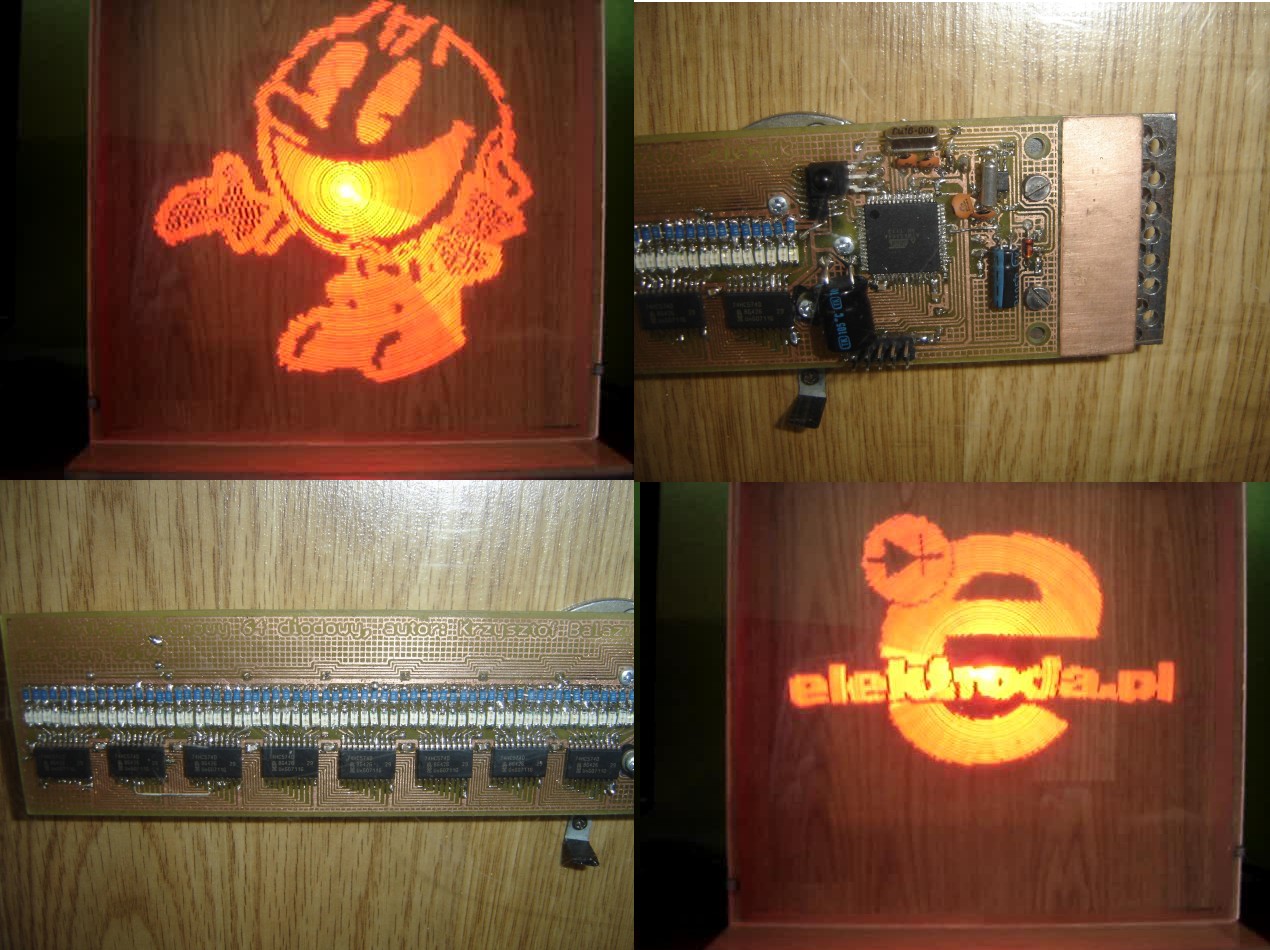
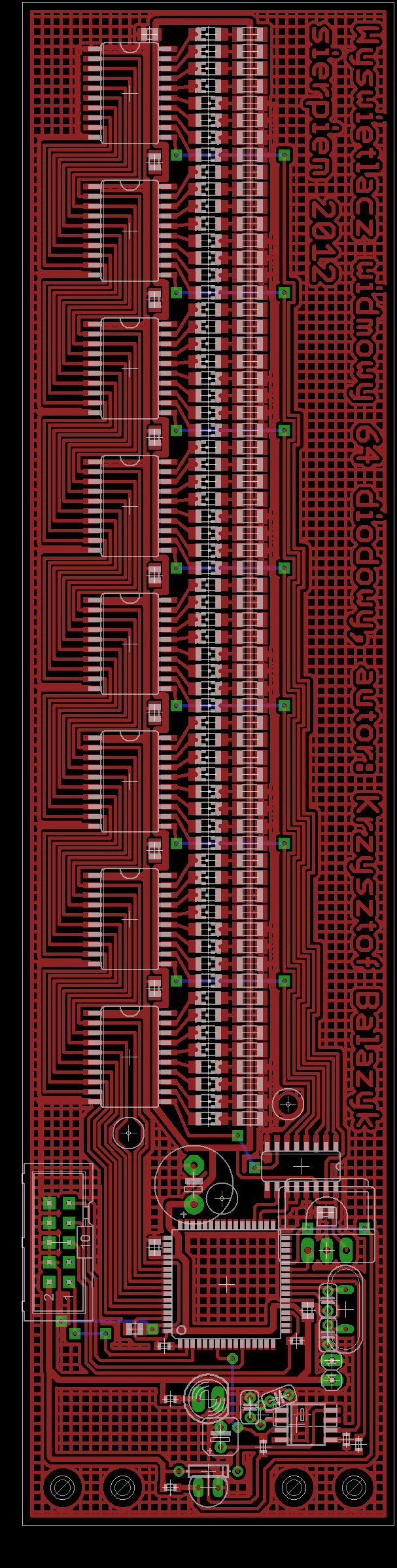
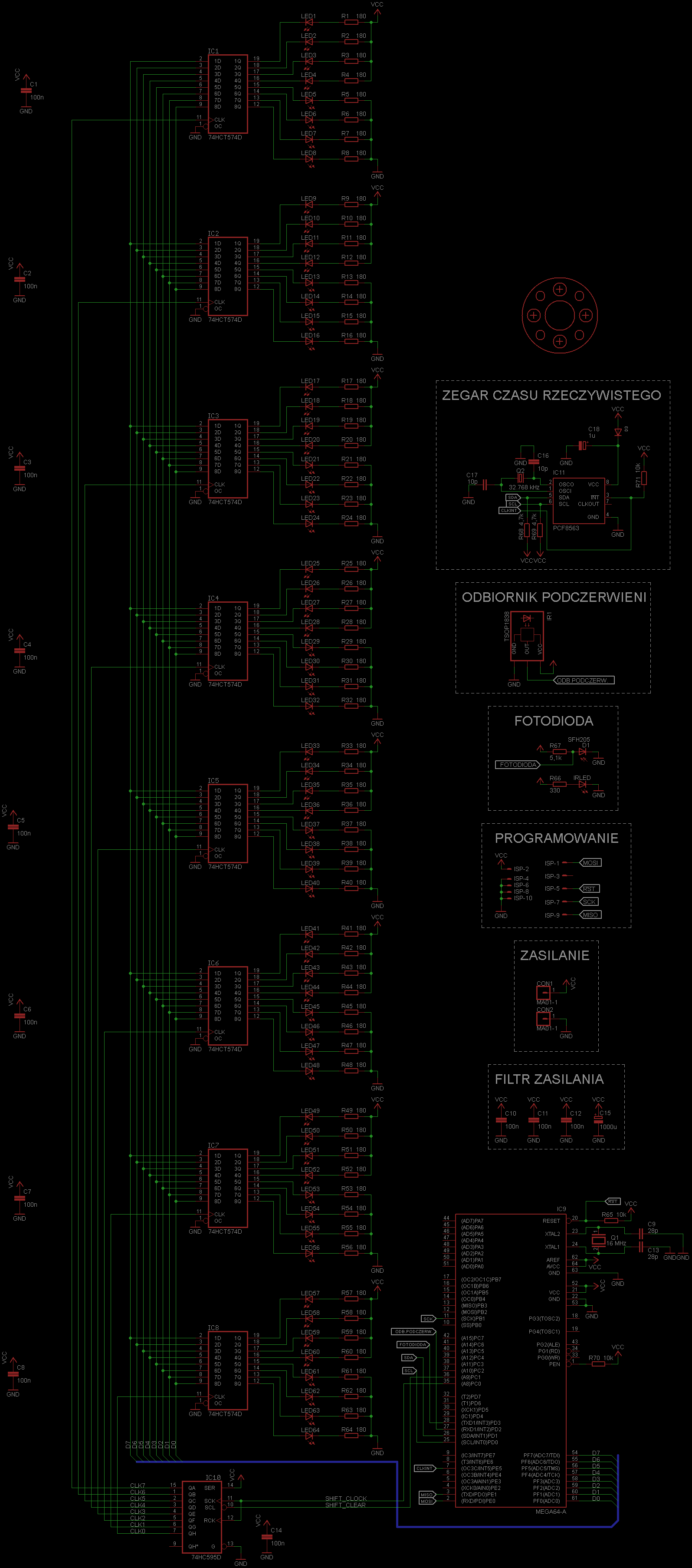
This design is a display implemented with use of 64 SMD diodes which are controlled by microcontroller Atmega64A.
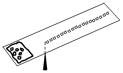
The previous version of the display looked like that:
The first version was made on a universal board with use of through hole diffused diodes. Due to the raster of the board, distance between the diodes was 2,54mm, what had an impact on the gaps between the circles. Moreover, they were the standard inexpensive diodes, so they did not give enough light in daylight, but thanks to mat casings, the quality of light was good.
Video of the final construction:
Another version was based on PCB with reduced gaps, but that effect was also not satisfactory. Using very bright diodes did not solve the problem, too. Their transparent casings caused that the best angle of lighting was while looking straight, and the light from the lighting diode was reflected in adjacent diodes.
The last version – technical details:
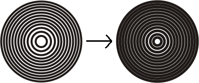
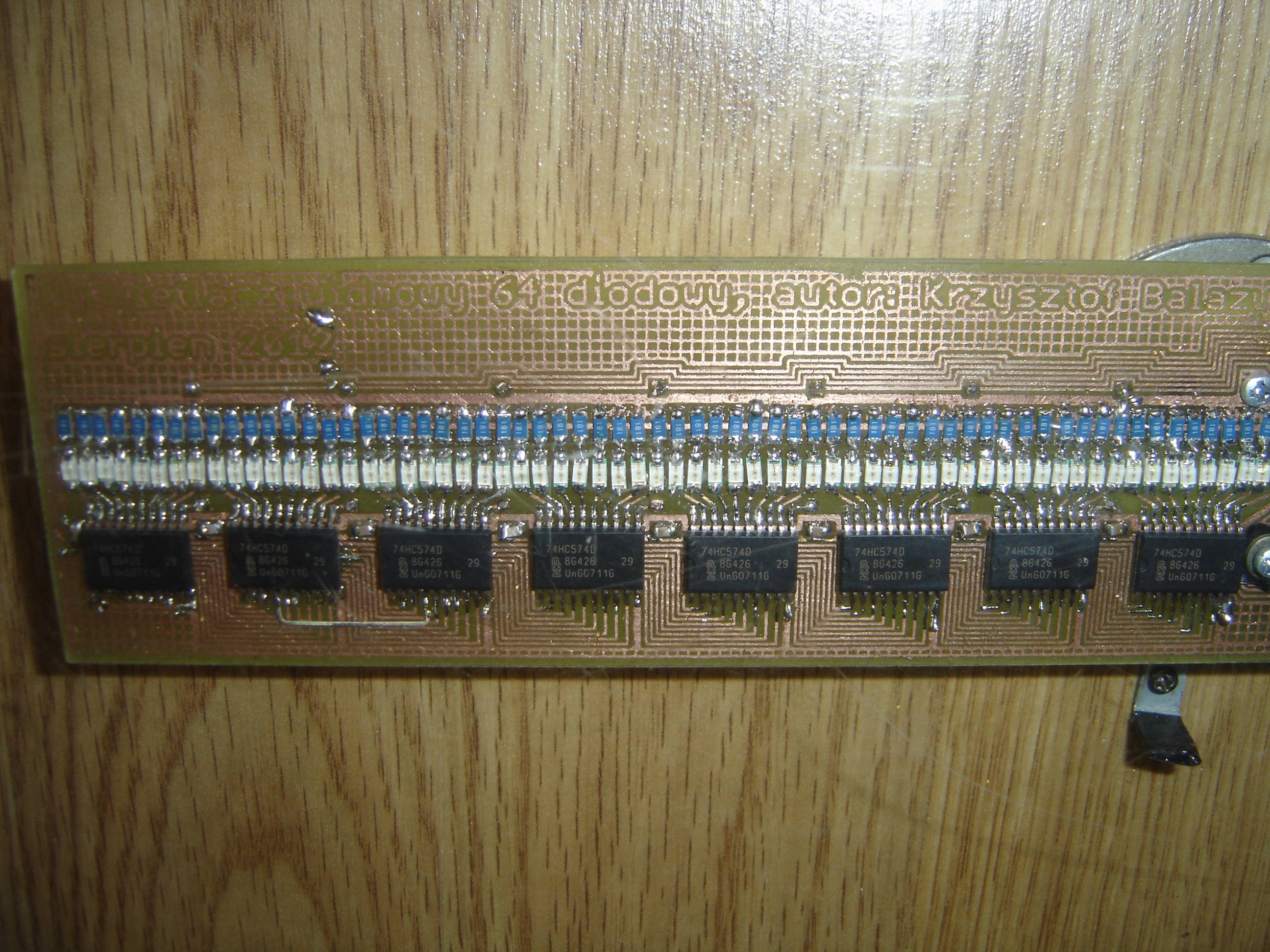
As it was mentioned before, this version is based on SMD diodes which are very bright and the angle of bright is almost 180”. Due to their size, the gaps between diodes were reduced to the minimum, what, when all diodes are lit, gives the impression of the whole circle lit, not the concentric circles.
Latches instead of shift registers:
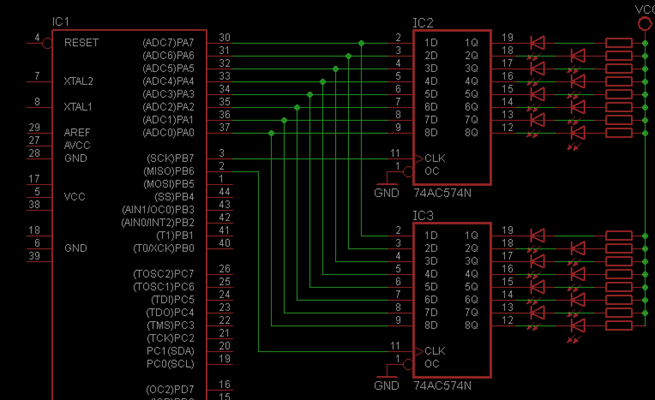
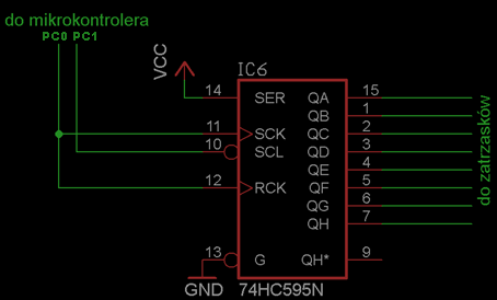
Another idea is diode control by means of latches 574. All the latches have common inputs and the data is latched in portions of 8 bits (not of 1, as while using shift register 595). Their clock slopes are controlled by shift register 595. Such connection of diodes engages only 10 microcontroller outputs, even when you want to connect more diodes, the number of pins remains the same. If the diode control used shift registers 595, setting the state on all diodes would require 64 shifts, so in the way it actually is performed, the number of commands is limited.
Diodes and their connection:

Diode current is limited by resistors 180R, what gives about 16mA. If all the diodes were lit, they would take 8 * 16 = 128mA, what could damage it (maximum allowable total current 80mA). The combination of half of the diodes in one side and the other half in the other side within a single latch makes that for all lit diodes 64mA flows from the latch through VCC, and the other 64mA flows through the GND.
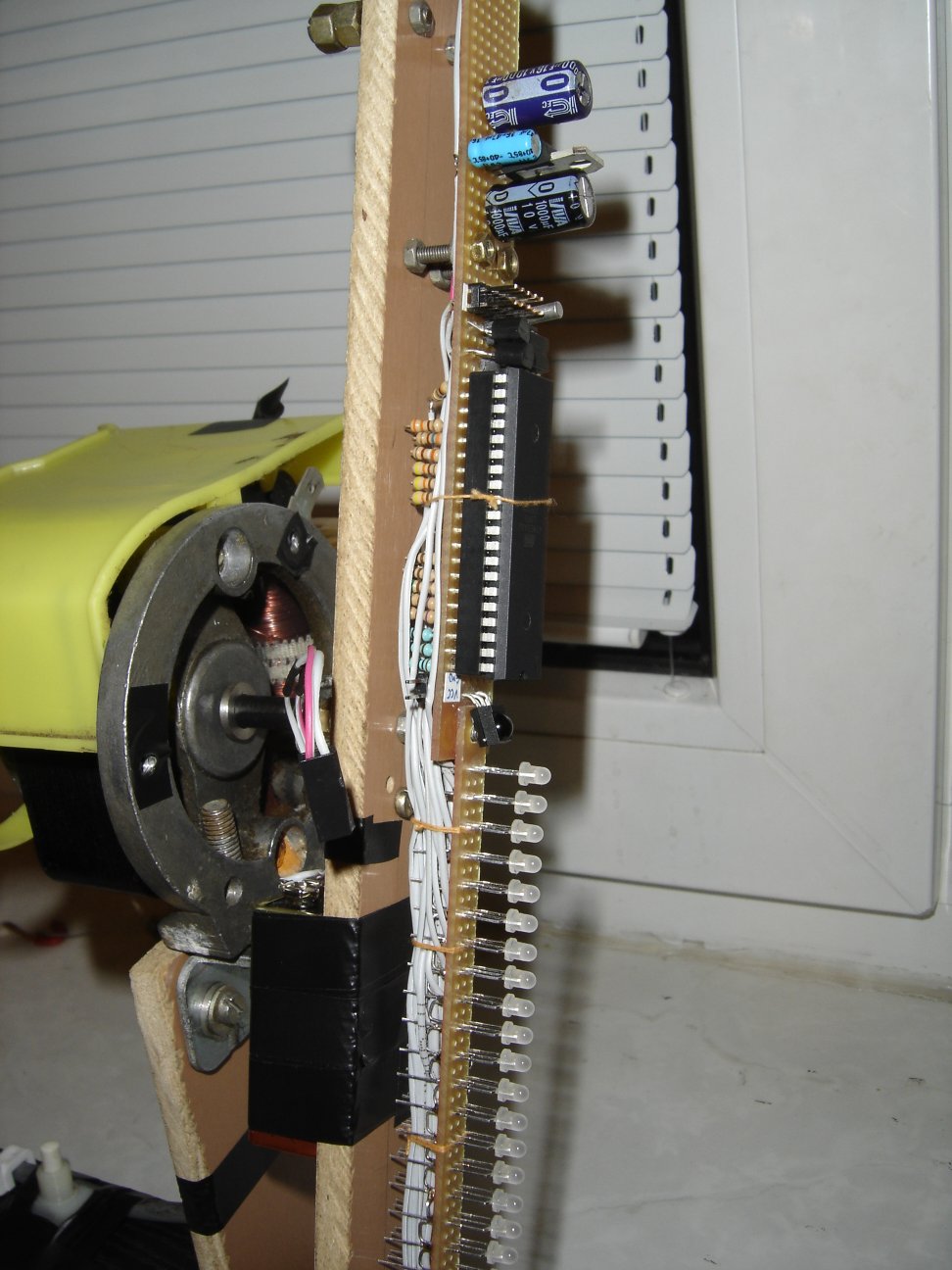
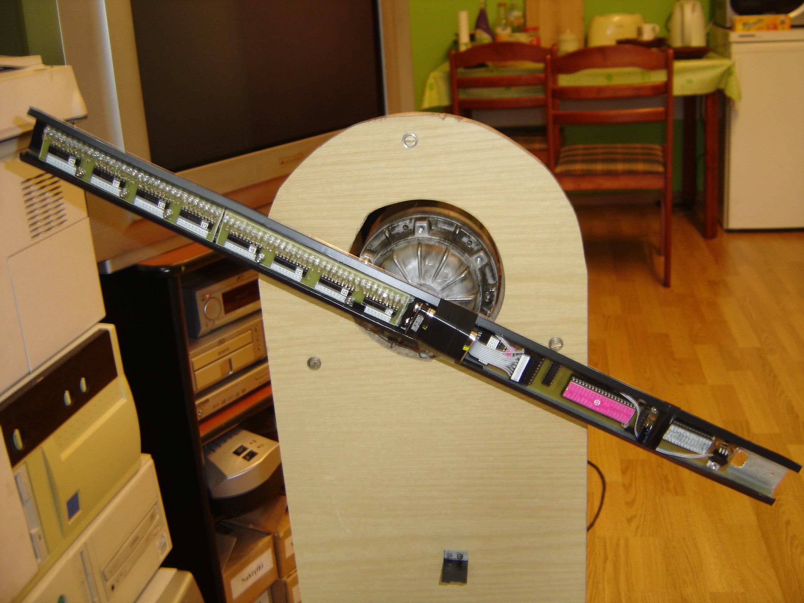
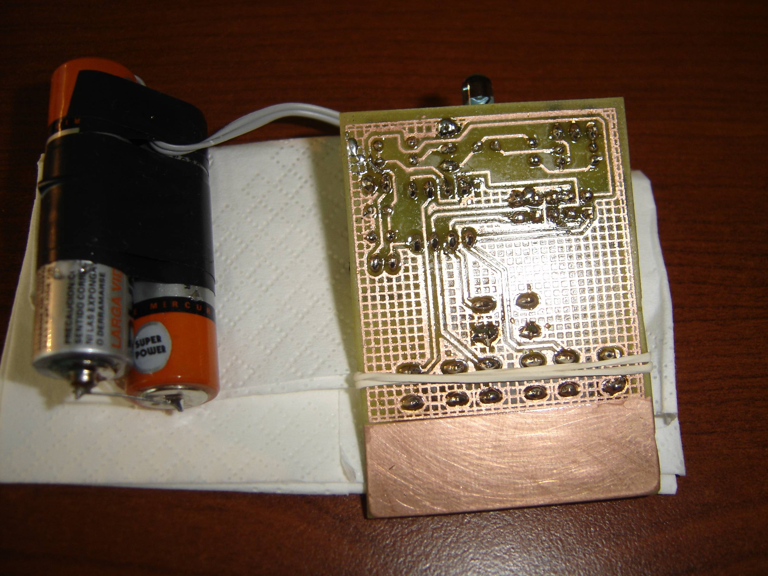
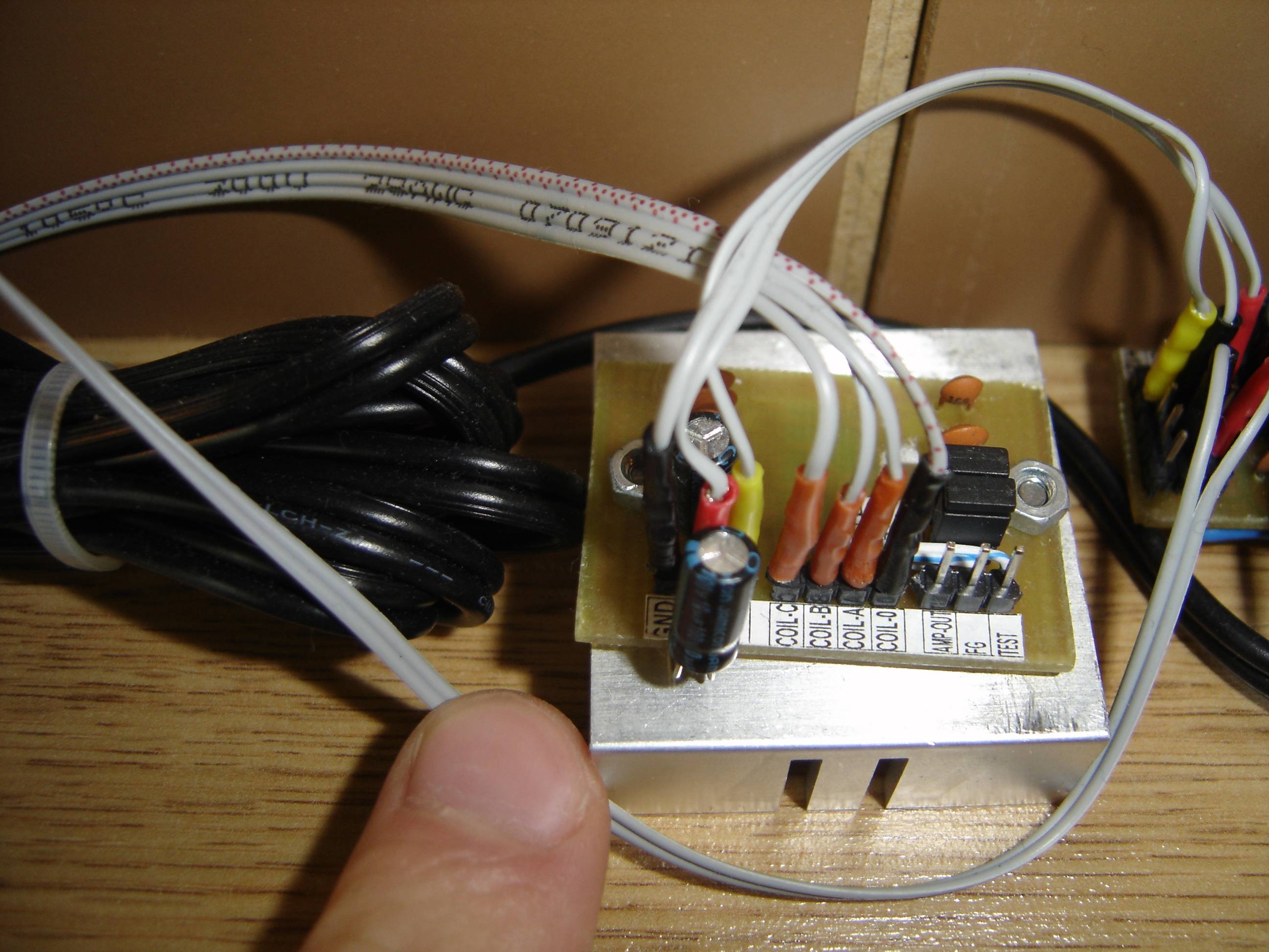
Motor:
The key element – motor – was removed from hard drive (three-phase brushless BLDC). Control with use of such a motor requires to generate three pseudo-sinusoids shifted in phase by 120 degrees. You will also have to provide the return information on the position of the rotor. It can be implemented by both Hall sensors or analysis of voltage on the third, winding inactive in the cycle (the so-called back EMF).
Chip circuit TDA5144 is used for the disk control. It is identical to TDA5140A, but has an increased maximum current up to 2A.
Analysis of position is provided by a photoresistor with constantly lighting IR diode. It is covered by a metal plate mounted to the construction, when the disk is in vertical position.
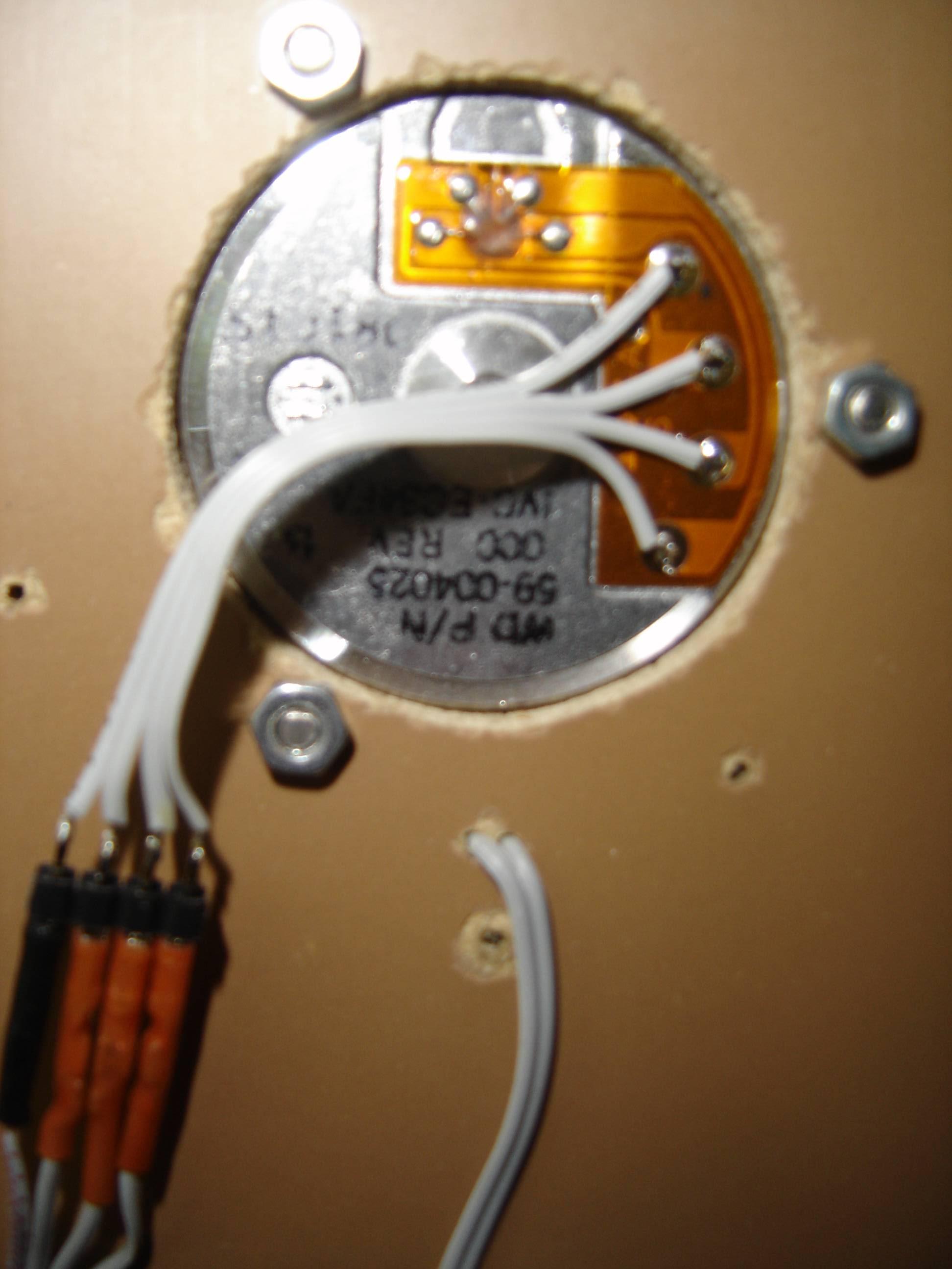
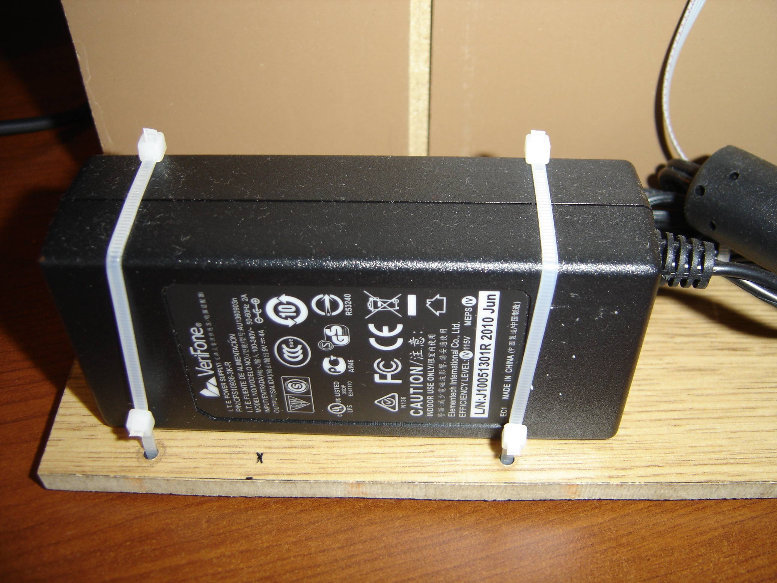
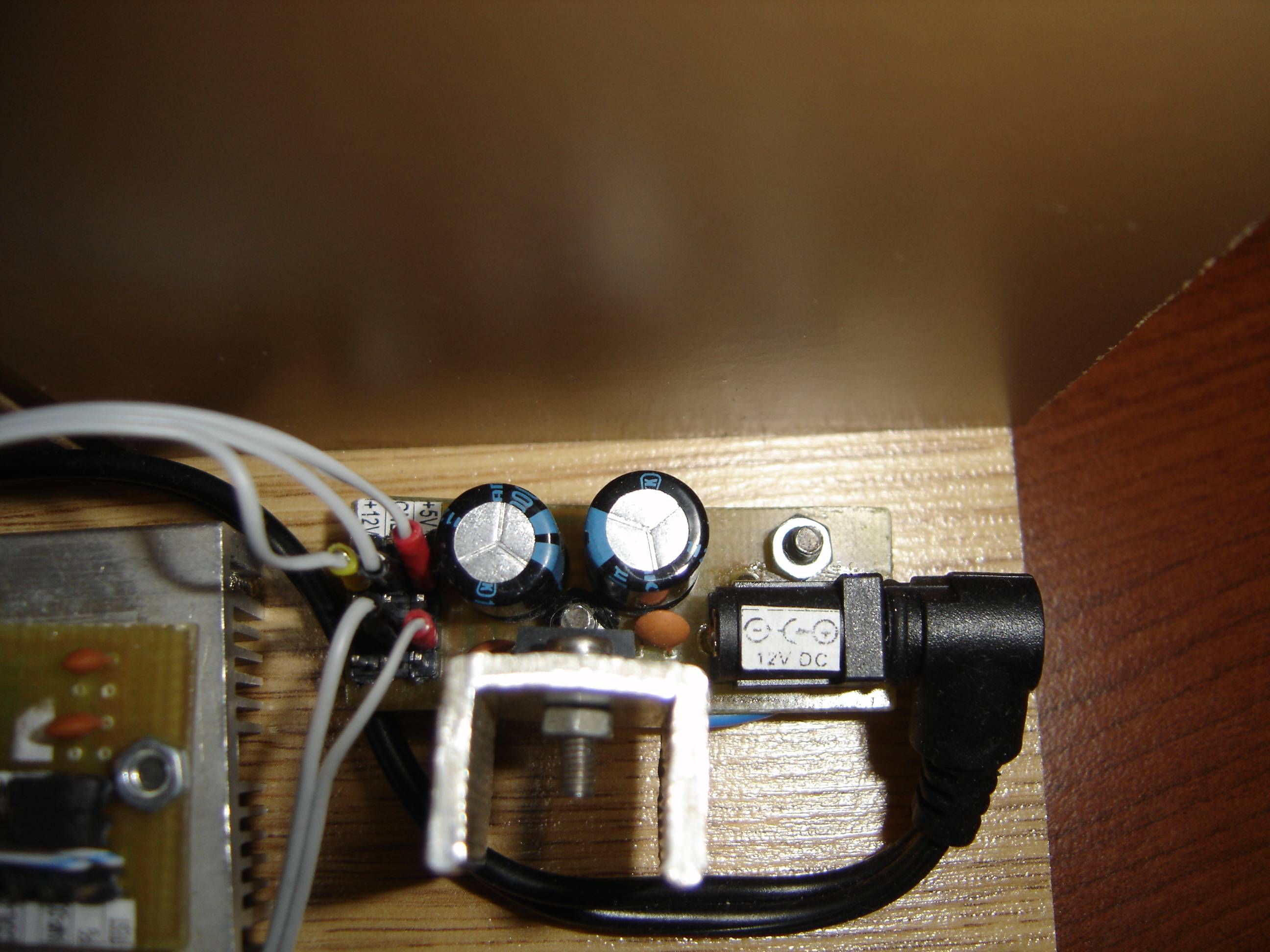
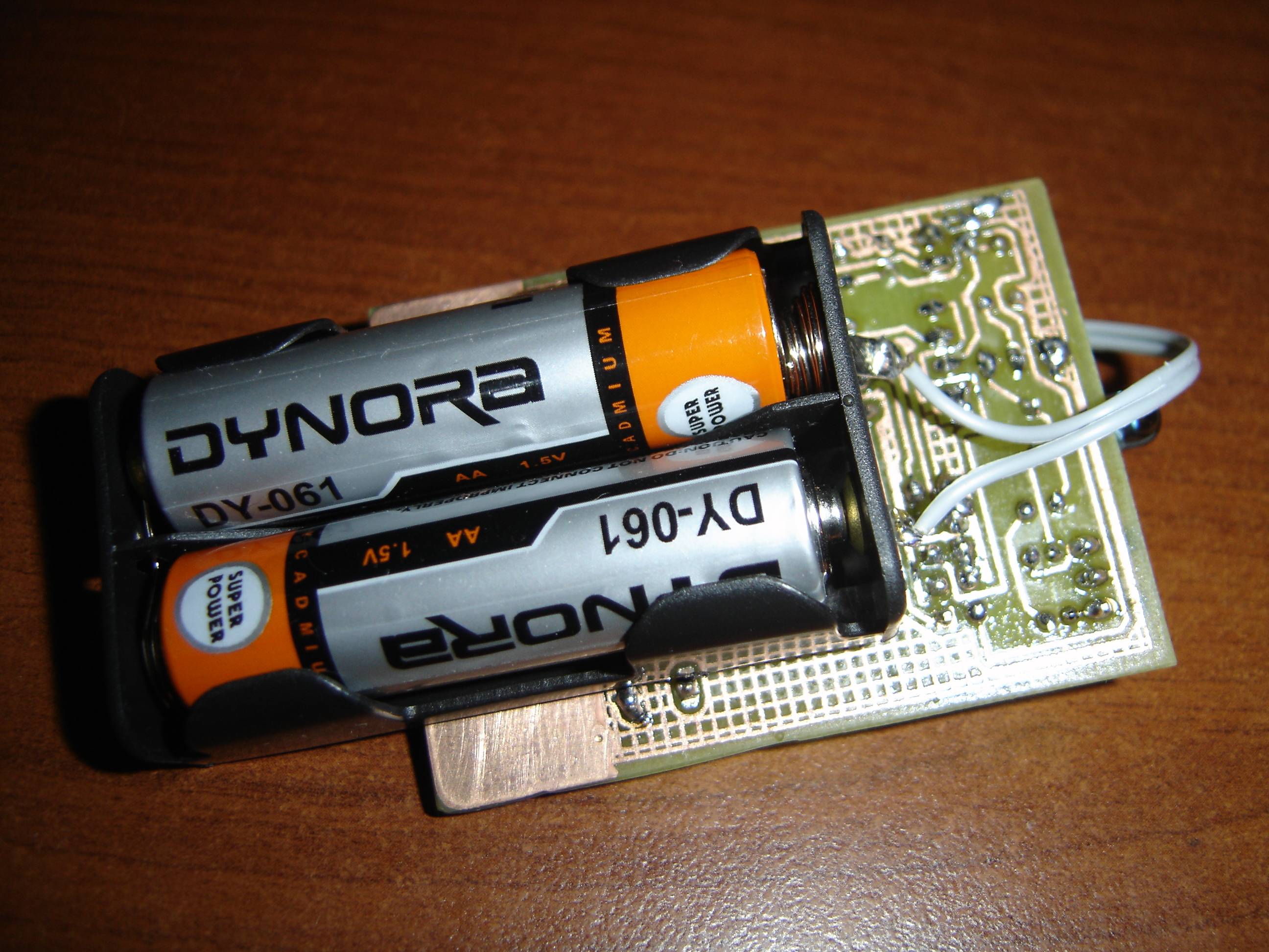
Power:
The energy passes through metal plates, rubbing against the isolated motor body (brush). The motor design is wrapped with insulating tape, which is wound with metal strap, against which the plate is rubbing. The strap was made of braided copper used for desoldering. Its ends can be easily soldered in shape of a ring or solder a wire. What more, this material provides resistance to abrasion.
The second brush (VCC) uses the same solution as for the ground.
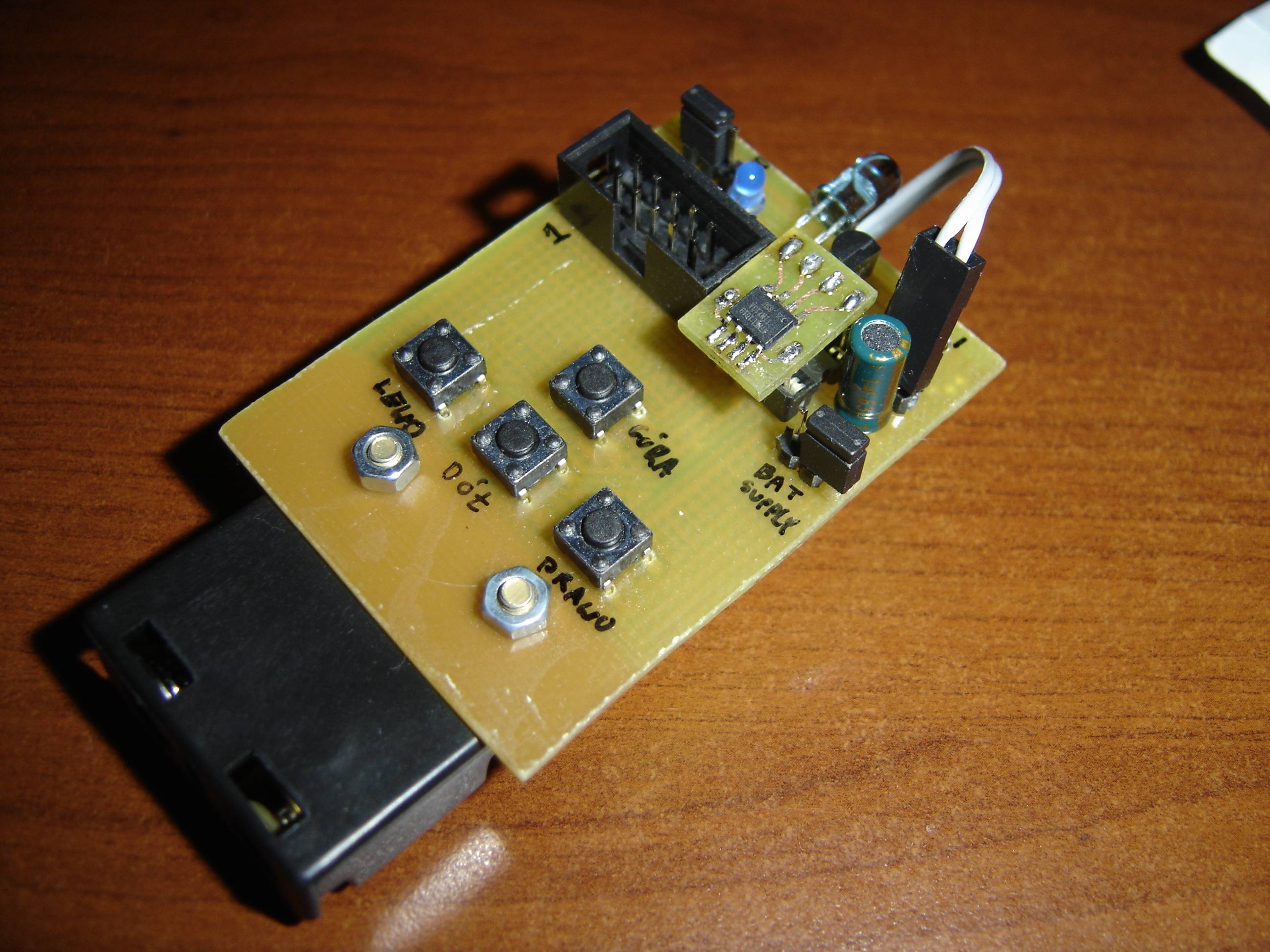
Other components:
There is a powerful capacitor (1000 uF) installed on the disk. It compensates for momentary power outages (poor contact of the plate). There is also an IR receiver used for sending commands to the disk and the RTC PCF8563.
Balancing the disk:
The disk should be balanced as well as it is possible. Its weight should be evenly distributed from the center. The center was selected to be located on the lowest diode, so that you can display an image that is a perfect circle. Since the disk on the side of diodes is much longer than on the opposite side, it was necessary to put additional weight on the shorter side – it was a heavy plate attached to it. If you want, you can attach a plate that is too heavy and gradually limit its size by drilling holes in it. In that way you can create a perfectly balanced rotor, which at high speed (2300rpm) do not have any vibration.
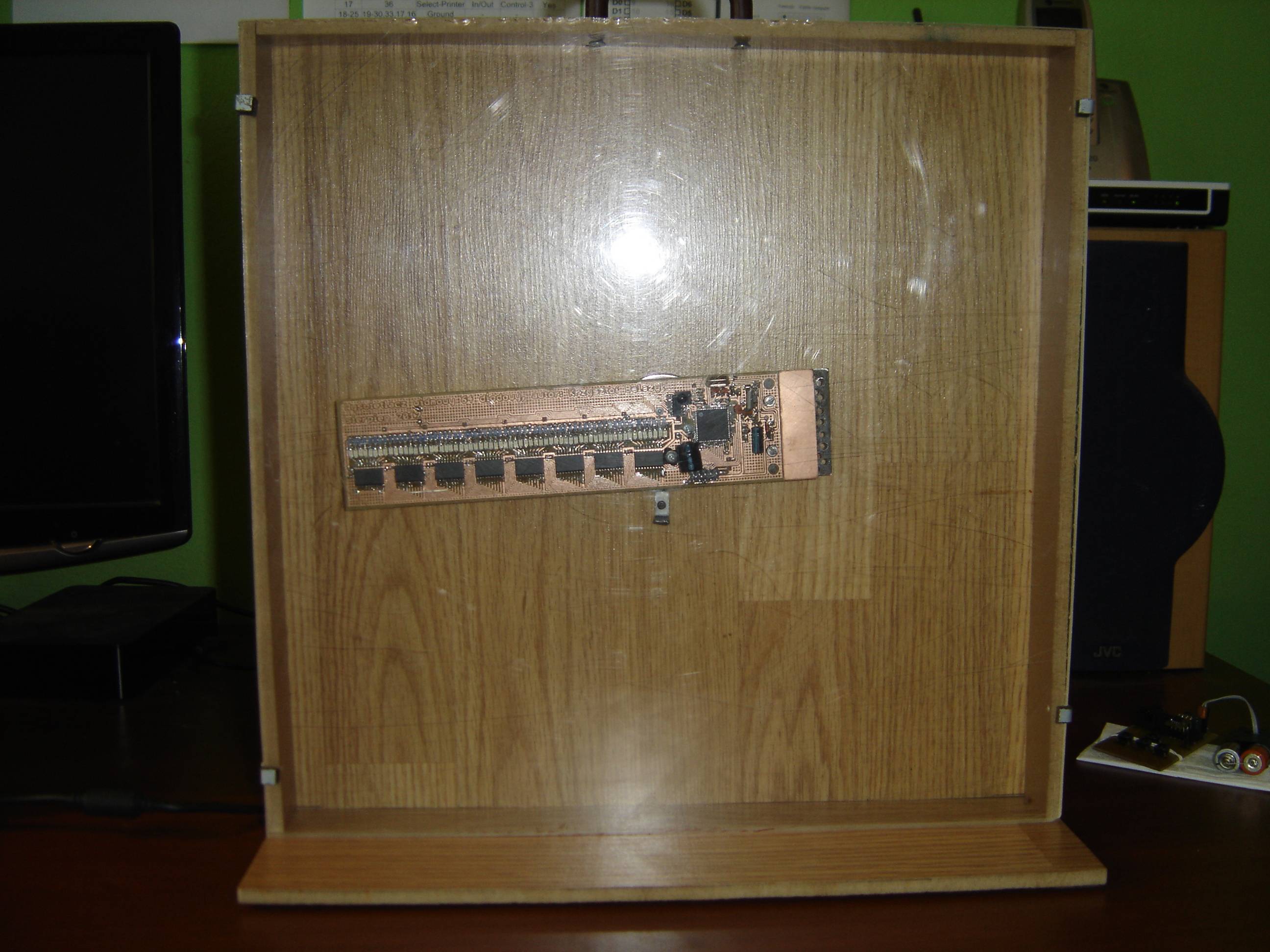
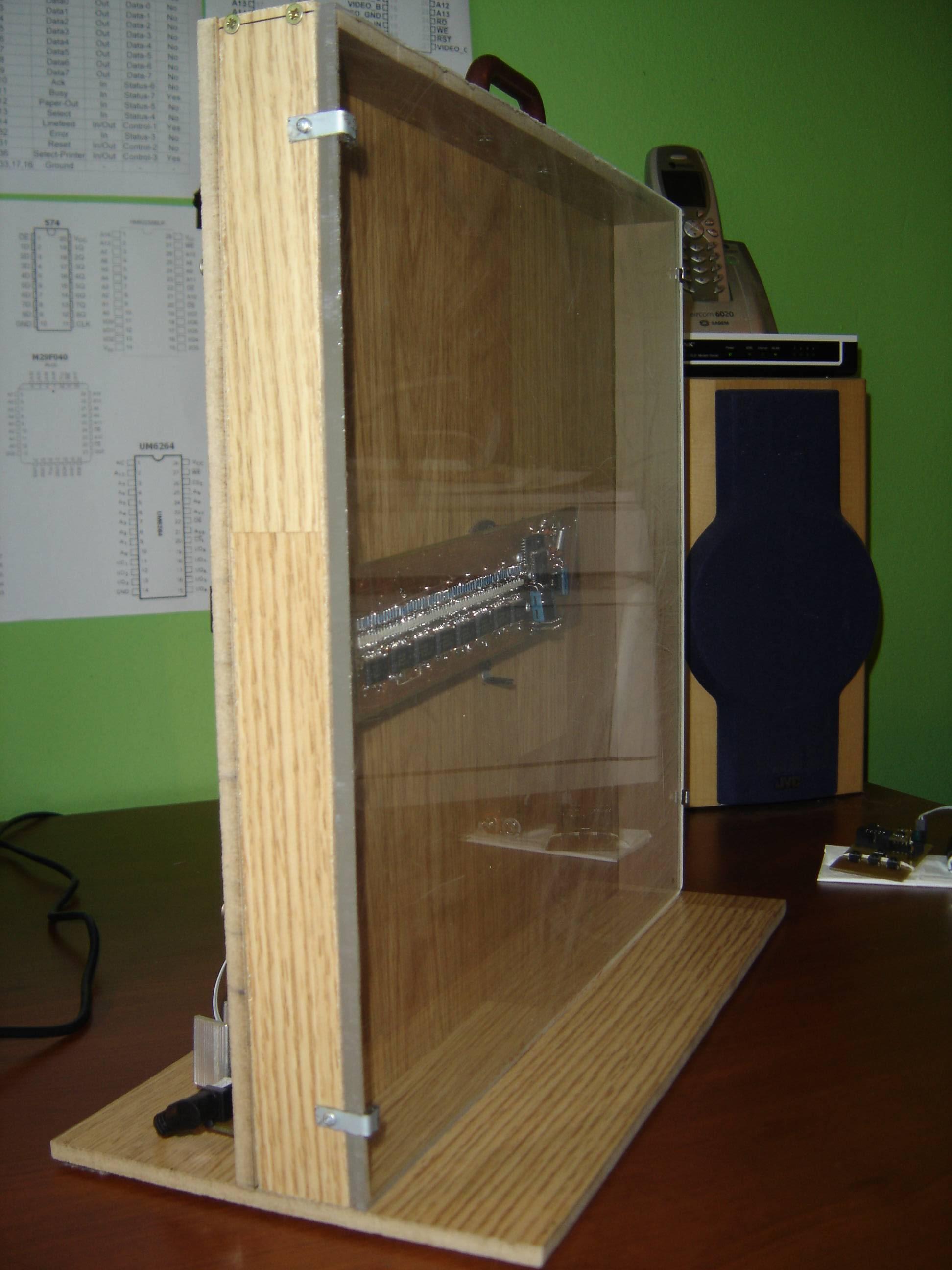
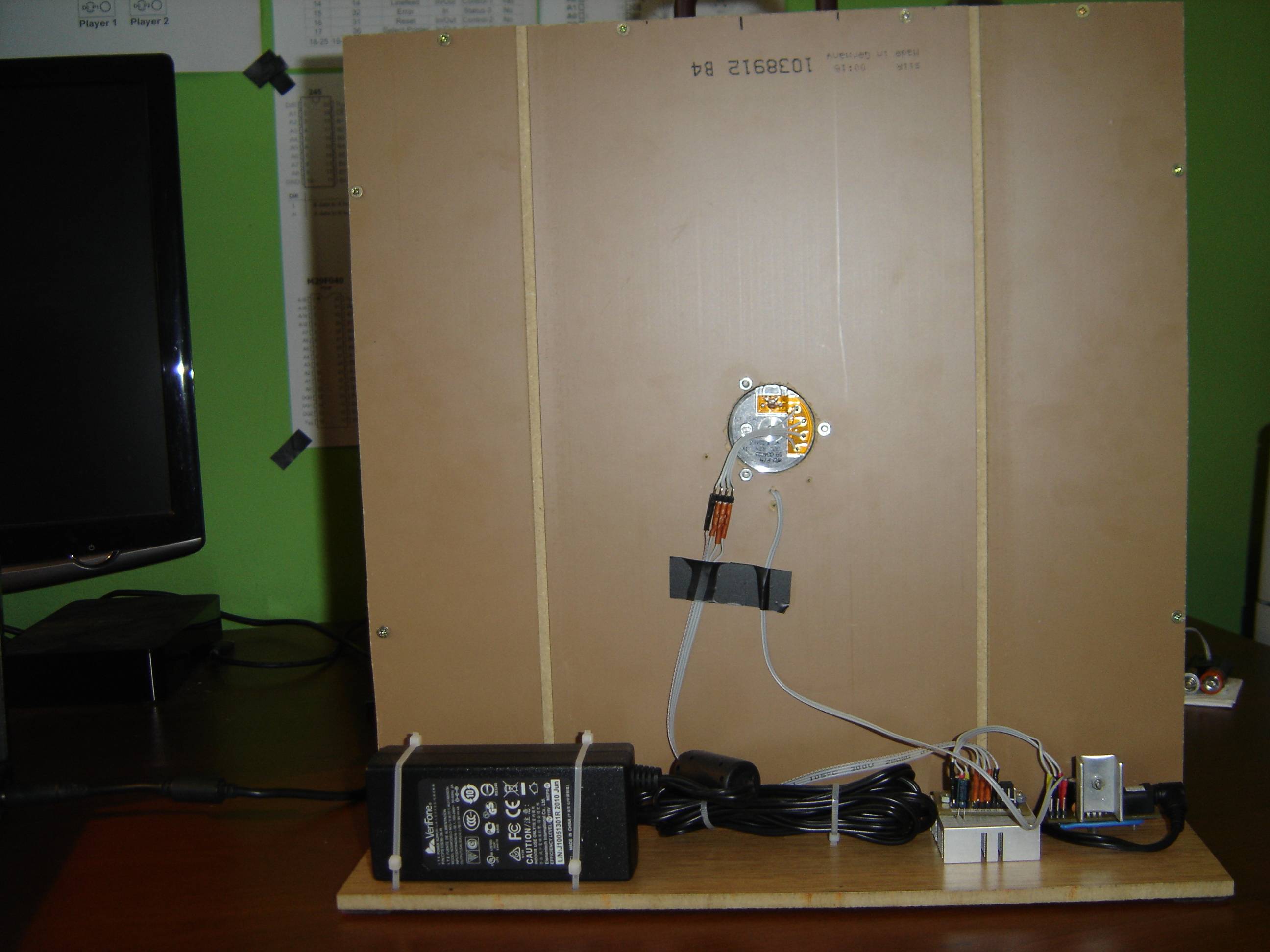
Wooden housing:
Wooden construction is another essential part of the design. It ensures protection against accidental touch and provides flexible shape. It was made of floor panels. Plexiglass was mounted on the front part of the housing to protect against touching.
Pictures:


Link to original thread - Ultra-duży wyświetlacz widmowy 64 LED SMD + Atmega 64 + PILOT