Vermes
Advanced Member level 4

- Joined
- Aug 2, 2011
- Messages
- 1,163
- Helped
- 0
- Reputation
- 0
- Reaction score
- 0
- Trophy points
- 1,316
- Activity points
- 22,318
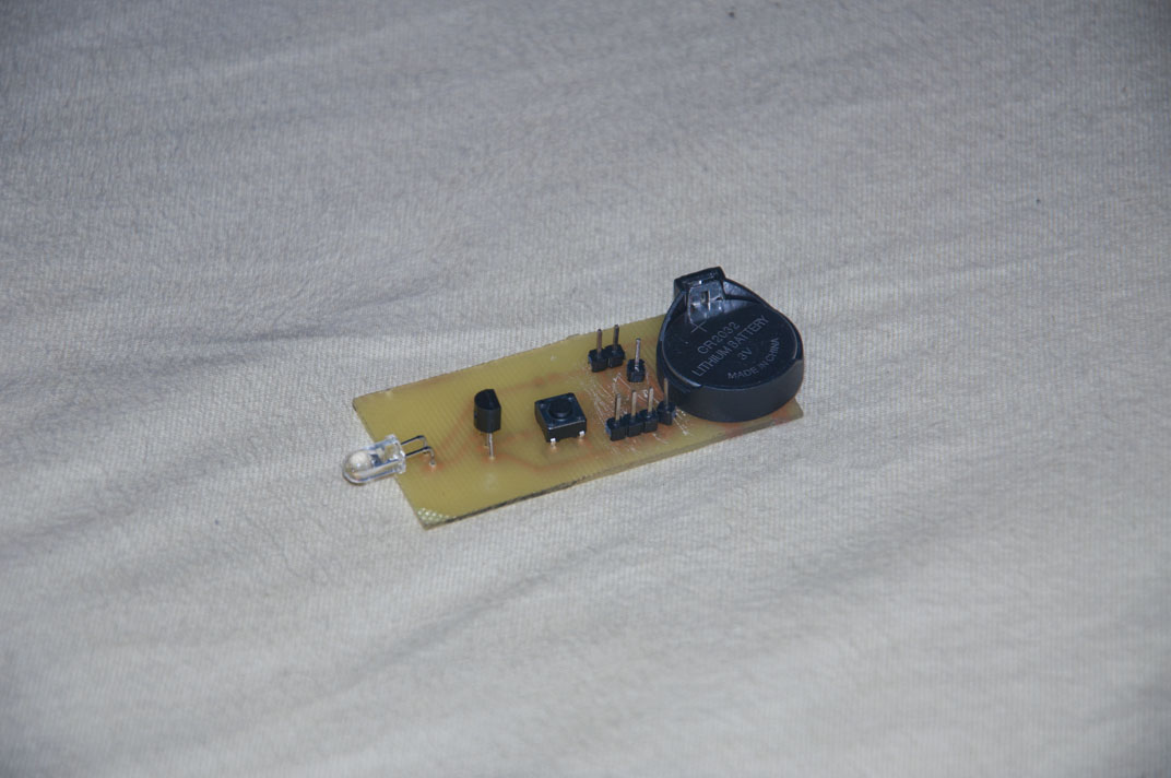
Presented here project of remote control for a camera, was based on design from this website:LINK. It was built on a smaller Attiny13, it could possibly be based on even smaller one such as available on the Internet Attiny4.
The principle of operation is very simple, so this device could be understood and constructed by beginners. After start of the timer and interrupts, Attiny switches to power-down mode, in which it waits for the interrupt pcint0 at the input PB1. After waking up, it sends an appropriate signal, which is amplified by the transistor and sent by IR diode to the camera. When the process of sending is over, the processor switches to power-down mode.
If you want to program it using the hex file from the attachment to the original thread, firstly you have to disable the prescaler of the oscillator. If you want to use the program at a lower frequency, you have to change F-CPU and and settings of the timer that generates 36kHz.
Of course, it is recommended to make a housing. The size of the board are 10x26x60mm.
Pictures:

Link to original thread (useful attachment) - Pilot do aparatu Nikon attiny13