Continue to Site

Welcome to EDAboard.com

Welcome to our site! EDAboard.com is an international Electronics Discussion Forum focused on EDA software, circuits, schematics, books, theory, papers, asic, pld, 8051, DSP, Network, RF, Analog Design, PCB, Service Manuals... and a whole lot more! To participate you need to register. Registration is free. Click here to register now.

uc controlled, zero-crossing, incandescent lamp dimmer

Status
Not open for further replies.

the_merovingian

Member level 1
Joined
Jul 25, 2009
Messages
32
Helped
0
Reputation
0
Reaction score
0
Trophy points
1,286
Location
UK
Activity points
1,558
I'm trying to design a circuit to dim an incandescent lamp (220V, 50Hz) from a microcontroller.

Ideally I'd like to use a transformer-less power supply consisting of current limiting resistors, rectification diode and a low current 5.6V zener diode.

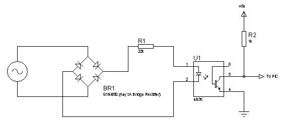
The bit I'm having trouble with is the zero-crossing detection, all the ZCD examples I can find use transformers and I was hoping to do this without due to the low power consumption required.

Any help (especially examples) would be appreciated.
 

Hi,
Try this zero-crossing detector. I use this for my 12F675 based lamp dimmer. It generates a high-to-low pulse every zero-crossing.
74_1263317766.jpg

Hope it helps.
Tahmid.
 
Hi,
Try this zero-crossing detector. I use this for my 12F675 based lamp dimmer. It generates a high-to-low pulse every zero-crossing.
74_1263317766.jpg

Hope it helps.
Tahmid.

Can you please explain why there is a need for resistor R2 and voltage of 5V?
 

Tahmid's circuit will not work (sorry Tahmid!). The concept is good but if you are deriving the 5V from the AC it requires modification. You would have to connect pins 2 and 4 of U1 together and use the point where the bridge rectifier and R1 meet to connect to your 5V supply components. I would suggest adding a diode in series with the 5V components to prevent the 5V draining back into the opto-coupler at zero crossing or it may not be detected properly.

BE EXTREMELY CAREFUL with any transformerless supply! They offer no isolation form the line AC so you must never connect any part of it to any other circuit or make it possible to touch any of the wiring, even if it appears to be low voltage.

Brian.
 

Hello...

Try this circuit....for the last two years i am using this circuit for Zero cross detection. The circuit gives very fine pulses. I got this circuit from google..Its 100% working...I made this circuit lots of time for different applications...You can use it for your application....
 

Attachments

  • ZCD.gif
    ZCD.gif
    18.5 KB · Views: 253

Again that will not work without modifiation. The OP asked for a transformerless supply with ZCD so there is no "isolated side", the voltage used at the output has to be derived directly from the incoming AC. That would be difficult with designs posted so far because their 'isolated supply' has to share a common rail with the line AC.

Brian.
 

The AN521 solution suggested in post #2 should basically do for the ZCD function. It's well compatible with intended "transformerless" supply, The essential point is to operate the processor power efficient and use a short triac trigger pulse to come along with a low power supply.
 

@felicia

When the transistor conducts the voltage across R2 is 5V which is logic 0 for PIC and when transistor is not conducting then voltage between PIC pin and GND is 5V which is logic 1 for PIC.
 

The circuit can be *much* simpler by using an opto like the PC814. This chip has 2 diodes in anti-parallel at the input, so the output triggers for both, the positive as well as the negative half-cycle, without needing a bridge at the input. Just use a 47K resistor at the input.

And Betwixt, you do not need to have the grounds shared between the input and the output; you do have true isolation.

Incidentally, I have been using this in my X10 receivers for years.

Regards,

Anand Dhuru
 

The circuit can be *much* simpler by using an opto like the PC814.
Generally a good suggestion, but applied to the wrong question.
 

ard - the request was specifically for a circuit that had no isolation, one that used no transformers. That changes the design because there is no 'ground' to reference the output of the opto to. It is necessary to estabilish a negative rail that is common to both sides of the optocoupler.

Brian.
 

Status
Not open for further replies.

Part and Inventory Search

Welcome to EDABoard.com

Sponsor

Back
Top