Continue to Site

Welcome to EDAboard.com

Welcome to our site! EDAboard.com is an international Electronics Discussion Forum focused on EDA software, circuits, schematics, books, theory, papers, asic, pld, 8051, DSP, Network, RF, Analog Design, PCB, Service Manuals... and a whole lot more! To participate you need to register. Registration is free. Click here to register now.

DAC MCP4725 controlled by STM32F103C8: Simulation not working properly

sbhanot030

Junior Member level 1
Joined
Sep 25, 2023
Messages
17
Helped
0
Reputation
0
Reaction score
0
Trophy points
1
Activity points
128
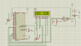
Hi all, I am executing a DAC(MCP4725) controlled by a micro controller(STM32F103C8) and displaying the values on a LCD screen, while running the simulation in Proteus The strings I wanted to display were displayed but the value which was to be read and displayed was not. The input is going into the DAC but no output is coming out so the final value is zero. Can someone please share where I am wrong. The original link of the project is https://circuitdigest.com/microcontroller-projects/how-to-use-dac-in-stm32f10c8

1699251378857.png


Code C - [expand]
1
2
3
4
5
6
7
8
9
10
11
12
13
14
15
16
17
18
19
20
21
22
23
24
25
26
27
28
29
30
31
32
33
34
35
36
37
38
39
40
41
42
43
44
45
46
47
48
49
50
51
52
53
54
55
56
57
58
#include<Wire.h>                   //Include Wire library for using I2C functions
 
#include<SoftWire.h>   
 
#include <LiquidCrystal.h>         //Include LCD library for using LCD display functions
#define MCP4725 0x60            //MCP4725 address as 0x60 Change yours accordingly
 
const int rs = PB11, en = PB10, d4 = PB0, d5 = PB1, d6 = PC13, d7 = PC14;
LiquidCrystal lcd(rs, en, d4, d5, d6, d7);
unsigned int adc;
byte buffer[3];                  
 
void setup()
{
  Wire.begin();                    //Begins the I2C communication
  lcd.begin(16,2);                 //Sets LCD in 16X2 Mode
  lcd.print("CIRCUIT DIGEST");  
  delay(1000);
  lcd.clear();
  lcd.setCursor(0,0);
  lcd.print("STM32F103C8");
  lcd.setCursor(0,1);
  lcd.print("DAC with MCP4725");
  delay(2000);
  lcd.clear();
}
void loop()
{
  buffer[0] = 0b01000000;            //Sets the buffer0 with control byte (010-Sets in Write mode)
  adc = analogRead(PA0);             //Read Analog value from pin PA0
  float ipvolt = (3.3/4096.0)* adc;  //Finding voltage formula
  buffer[1] = adc >> 4;              //Puts the most significant bit values
  buffer[2] = adc << 4;              //Puts the Least significant bit values
  unsigned int analogread = analogRead(PA1) ; //Reads analog value from PA1
  float opvolt = (3.3/4096.0)* analogread; //Finding Voltage Formula
 
  Wire.beginTransmission(MCP4725);         //Joins I2C bus with MCP4725 with 0x60 address
  Wire.write(buffer[0]);            //Sends the control byte to I2C
  Wire.write(buffer[1]);            //Sends the MSB to I2C
  Wire.write(buffer[2]);            //Sends the LSB to I2C
  Wire.endTransmission();           //Ends the transmission
 
  lcd.setCursor(0,0);    
  lcd.print("A IP:");
  lcd.print(adc);                   //Prints the ADC value from PA0
  lcd.setCursor(10,0);
  lcd.print("V:");                  //Prints the Input Voltage at PA0
  lcd.print(ipvolt);
  lcd.setCursor(0,1);
  lcd.print("D OP:");
  lcd.print(analogread);             //Prints the ADC value from PA1 (From DAC)
  lcd.setCursor(10,1);
  lcd.print("V:");
  lcd.print(opvolt);                 //Prints the Input Voltage at PA1 (From DAC)
  delay(500);
  lcd.clear();
 
}


Attachments

  • 1699250872277.png
    1699250872277.png
    57.5 KB · Views: 61
Last edited by a moderator:
Solution
Hi,

from code post#1:
#define MCP4725 0x60 //MCP4725 address as 0x60 Change yours accordingly

This does not match the selected address option of 0xA0

This is why they wrote "Change yours accordingly"

Klaus
Your 1K pullups on the SDA and SCLK lines kind of low, more traditionally
one sees ~ 4.7K or so. You might be compromising levels on the I2C interface.

https://www.ti.com/lit/an/slva689/slva689.pdf

Note MCP4725 datasheet calls out a typical 10K. Also some might be tempted to
use internal pullups on GPIO, dont, they are worst case 50K and would compromise
timing.


Regards, Dana.
 
You did not mention what MCP4725x variant you are using.
Depending on which one, the device address may change and therefore the code itself ( #define MCP4725 ... ).
I guess it is available by double-clicking the component as a configurable option on Proteus schematic.
 
Hi sorry for the late reply, but while selecting the component there was no mention of the variation of the mcp4725. only the packaging was mentioned,
1701170022988.png
 
Hi,

from code post#1:
#define MCP4725 0x60 //MCP4725 address as 0x60 Change yours accordingly

This does not match the selected address option of 0xA0

This is why they wrote "Change yours accordingly"

Klaus
 
Solution
Hi,

from code post#1:


This does not match the selected address option of 0xA0

This is why they wrote "Change yours accordingly"

Klaus
Hi, yeah the mode 0x60 was set for A0 connected to ground. The address byte changes from 0x60 to 0x67 for a variety of modes of operation. I also had a doubt that why have you mentioned 0xA0 as an address option and where I selected it because in the code I could not find it
 
Hi


post#4 --> picture --> Advanced Properties --> Address option --> A0

Klaus
I did try this but this did not work, The string lines are displayed and if I take constant inputs instead of using analogRead command then also the result is displayed on the LCD screen
 

LaTeX Commands Quick-Menu:

Part and Inventory Search

Welcome to EDABoard.com

Sponsor

Back
Top