shemo
Advanced Member level 4

- Joined
- Apr 26, 2002
- Messages
- 105
- Helped
- 0
- Reputation
- 0
- Reaction score
- 0
- Trophy points
- 1,296
- Activity points
- 709
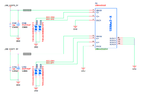
1) 1.png, the ESD diodes looks like two regular diodes in reverse. Then how can it conduct any current? one of them would block it?
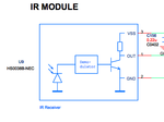
2)2.png, IR module, there is photo diode there but the plus side is tied to end. so when will it conducting?
3)3.png, there are no caps in LINEINL, LINEINR, are the caps purpose are to block DC?
only AC signals coming in?
4)4.png, what's 600R-100M means for the Ferrite bead? R133, R134, R135 with cap are the bypassing path to filter any AC noise for the DC power source?
Is the cap is to filter noise then would the ferrite beads redundant?
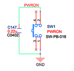
5)5.png, when pressed, the path brining the PWRON signal to GND. what's the purpose of that?
6)6.png, when NMI# active low is on, D4 is on then quickly bringing NMI# back to high , is that purpose is to make sure NMI# stays low only for a short time?


