Welcome to our site! EDAboard.com is an international Electronics Discussion Forum focused on EDA software, circuits, schematics, books, theory, papers, asic, pld, 8051, DSP, Network, RF, Analog Design, PCB, Service Manuals... and a whole lot more! To participate you need to register. Registration is free. Click here to register now.
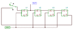
Mister_rf thanks for your reply. Your circuit with the DFF assumes we'll always about ~4 pulses? I had failed to point out that we have an unknown number of pulses ...
I'm interested in understanding how to implement for both. I have been playing with a technique with an SR-latch ... latching on the rising edge and then switching to a "high state" so the output stays high ..., but that's still under investigation. Any further ideas are welcome ... thanks!
This is why you should explain in detail what you want.
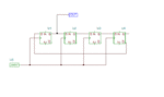
In this case there was only a sketch with four pulses and a second pulse with duration of four clocks and you have asked how to implement it, naturally you got an answer for exactly that.
So take your time when you ask questions and write what you want, no one can guess what your actual need.
This is why you should explain in detail what you want.
In this case there was only a sketch with four pulses and a second pulse with duration of four clocks and you have asked how to implement it, naturally you got an answer for exactly that.
So take your time when you ask questions and write what you want, no one can guess what your actual need.
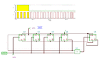
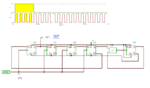
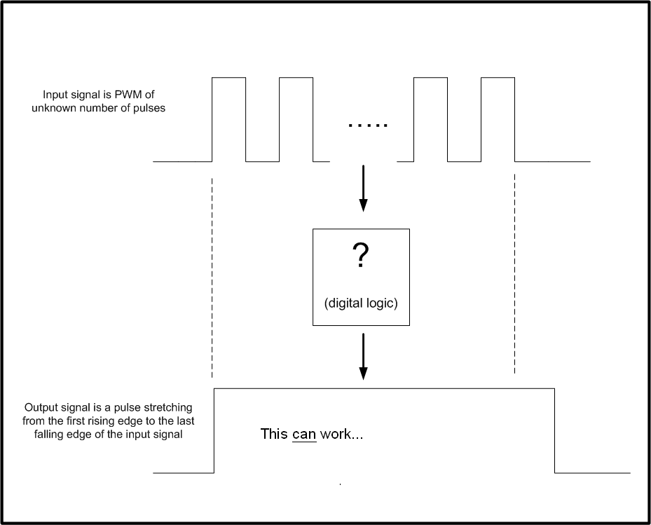
Yes, I have drawn a better picture and description. What I was trying to express is that the width of the output pulse should stretch from the first rising edge to the last falling edge as I have shown on the picture. I'm sorry for not presenting this in a better way :/
You can’t put in practice a circuit to follow this description. If we use an unknown number of pulses, how come you can predict when it's time the signal to stop?
A feasible cicrcuit with a similar behaviour is a retrigerable pulse stretching monoflop. But of course, the output pulse must exceed the last falling input edge by some time amount. I hope, the explanation by mister_rf has been clear in this regard.
This site uses cookies to help personalise content, tailor your experience and to keep you logged in if you register.
By continuing to use this site, you are consenting to our use of cookies.