Continue to Site

Welcome to EDAboard.com

Welcome to our site! EDAboard.com is an international Electronics Discussion Forum focused on EDA software, circuits, schematics, books, theory, papers, asic, pld, 8051, DSP, Network, RF, Analog Design, PCB, Service Manuals... and a whole lot more! To participate you need to register. Registration is free. Click here to register now.

Transistor to drive a DC motor

Status
Not open for further replies.

wcz

Member level 2
Joined
Jul 17, 2004
Messages
49
Helped
0
Reputation
0
Reaction score
0
Trophy points
1,286
Activity points
582
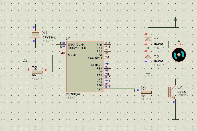
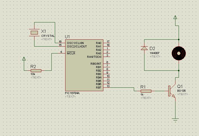
I would like to run a dc motor, no speed control, no direction requires. Any problem with the circuit i gonna build?
PB7 is the output pin of microcontroller.
Thanks for advice.
 

this circuit work but to small motor, what the voltage and corrent have your DC motor?
 

depending on the current of the motor.

usualy i use 5v 1A SPST relay controlled by a transistor driver 2n222 or any general purpose transistor.

β

Added after 16 minutes:

with that circuit the transistor will not last long....:!:

use that circuit to control the relay as i have said earlier.

:D

β
 

with that circuit the transistor will not last long....

use that circuit to control the relay as i have said earlier.

Normally its better to use power transistors than relays
If you use reallys then there are problems of noise, chattering, mechanical life of relay, mounting space required

As asked before you should provide voltage and current ratings or reuirements so that one can recommend a transistor
 

The inductive kick from turning the motor off may damage your transistor. Put a diode across the motor pointing up ( conducting in the opposite direction). It should be rated for the motor current.

As stated above, the BJT can be replaced by a power MOSFET.
 

    wcz

    Points: 2
    Helpful Answer Positive Rating
specification of the motor such as load current is much needed to provide the correct driver for such application.

"simplest design is the best design"
 

Here are the specification of the motor.
Torque: Low
Operating Volts: 1.5- 4.5V
Nominal Volts: 3V
Speed (no load): 12000rpm
Current (no load): 0.28A
Speed (max eff): 8540rpm
Current (max eff): 0.69A
Torque (max eff): 7.94gcm

Any recommendation?
 

The 2N2222 is just to small for this job, so you shold select a transistor with Ic between 1.5-2A, such as ZTX651/3, BD135/7, or similar..
Regards,
IanP
 

    wcz

    Points: 2
    Helpful Answer Positive Rating
the following circuit (just quickly drawn in paint) is a great solution to get a
very linear high-current motor control.

by op-amp golden rules, the inverting input of the op-amp is driven to equal the +input, therefor your current through the motor is set by Vin / R.

I used this in a MagLev system to drive a high-current electromagnet coil and it worked a charm - let me know if it worked for you!

best of luck,
gvanto
 

Hi guys, i've a problem here.
i cannot make the dc motor moving on the circuit i suggested.
however, when i put a LED series with the dc motor, the led will be switched on, not the dc motor.
what is the problem?
 

You shoul use darlington connection with 2N2222 and BD 135 for example.
 

Have you tried the op-amp feedback circuit from above? It sounds like you're not getting enough current through your motor...

Anywayz, a simple LM324 and i think a STPNE60 for the mosFET (or something to these lines) do the trick nicely.

good luck,
gvanto
 

What is the value of R in your circuit?
It might be limiting the starting current or required current for DC motor to flow
 

did you do what flatulent suggested?

this is a stupid question, but you have a DC permanent magnet type motor right?

can your power supply, VCC, suport a MINIMUM of 1.5A? your motor will request this at startup.

Mr.Cool
 

Sorry guys for no response. Actually it did work. The problem is that, the battery ran out of ENERGY!
I bought a new one and all the motors are moving. Thanks for all who helped.
 

Hi all
I use bd135 to drive a dc motor with pic microcontroler
I use dc motopr with LED parallely.
It work fine with LED but
when i use it with a dc motor the led period change
and after some second the Led turn off and dc motor stop working
I use following program
compiler is mikoroelectronika

void main() {
TRISB=0;
while(1){
PORTB=0XFF;
Delay_ms(10);
PORTB=0;
Delay_ms(200);
}

}

can anyone help me??
my power is 5V-500mAmper
I guess it is because of my power supply
:cry:
 

The LED period changes bcz the motor works as Generator when the switch is open.

The controller goes OFF bcz of the Back emf use diode in reverse bias configrature across the motor to kill the inductive kicks
 

I use

Added after 3 minutes:

I use two diode and simulate the circuit in proteus
in proteus it work well but in real it first round with periodical speed and after some second it round fast
and after some second stop
I dont know why?
this is the circuit i use


Added after 11 minutes:

I test the following circuit too
but the result is that after some second the dc motor stop working
can any one give me the schematic of diod and dc motor circuit
??
please help
 

please help me
i dont know why it does not work
 

in second diagram the diode is connected in a right way

Replace R2 10k by 4.7k,
u r driving ur motor & controller via 5v Regulator ??

whatz the specification of ur motor
V?
I?
 

Status
Not open for further replies.

Similar threads

Part and Inventory Search

Welcome to EDABoard.com

Sponsor

Back
Top