Continue to Site

Welcome to EDAboard.com

Welcome to our site! EDAboard.com is an international Electronics Discussion Forum focused on EDA software, circuits, schematics, books, theory, papers, asic, pld, 8051, DSP, Network, RF, Analog Design, PCB, Service Manuals... and a whole lot more! To participate you need to register. Registration is free. Click here to register now.

Transistor as a switch

Status
Not open for further replies.

omerysmi

Member level 5
Joined
Oct 10, 2014
Messages
91
Helped
0
Reputation
0
Reaction score
0
Trophy points
6
Activity points
1,128
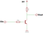
Look at this circuit:

TRANSISTOR.png

I have to find a way that when Vin is "0" Vout will be 0V and when Vin is "1" Vout will 5V.

"1" -> 5V
"0" -> 0V

As you see, right now is exactly the opposite of what I want, do you have some idea how to do it without many changes?
 

Hi,

the bjt in this common emitter circuit acts like an inverter.

--> use an emitter-follower circuit. But the outut voltages are 0V / 4.4V (instead of 5V) in best case.

Klaus
 

Hi,

the bjt in this common emitter circuit acts like an inverter.

--> use an emitter-follower circuit. But the outut voltages are 0V / 4.4V (instead of 5V) in best case.

Klaus

why 4.4V???
 

Hi,

Why now 30V? You only mentioned 5V...

Generally you can not expect a higher output voltage than your supply voltage.

But in your case it´s worse, because with emitter followers:
--> V_emm = V_base - V_BE = 5V - 0.6V = 4.4V.

Klaus
 

- - - Updated - - -

Hi,

Why now 30V? You only mentioned 5V...

Generally you can not expect a higher output voltage than your supply voltage.

But in your case it´s worse, because with emitter followers:
--> V_emm = V_base - V_BE = 5V - 0.6V = 4.4V.

Klaus
When i think about it again, your idea is not very good for me because i need to pass high voltage (30V). I thought is not important to mention it but now i think different :bang:

So assume that i have 30V in the collector of the transistor, and Vin is some I/O port (0/5V).

TRANSISTOR.png

"1" - > 30V
"0" -> 0V
 
Last edited:

A "common base" configuration - adding one resistor and
making a divider with about a 1.2V center tap, connected
to BJT base, and applying the control voltage (you did not
say whether "0" and "1" are voltage, or logic) to the BJT
emitter terminal would do what you (say you) want, provided
that the control voltage is stiff enough to provide the needed
emitter current to pull the load (in which case your VOL will
be =Vin+Vce(sat).

This is how the front ends of old-timey TTL were made.
 

Here's an LTspice simulation of Dick's circuit (as I understand it).
As noted the input must be capable of sinking the current through the load resistor R1+R2 (in this case, about 1.1mA).

Capture.PNG
 
Rather u could use an PNP Transistor to achieve the same ,, the Voltage a the output would be close to 5V depending on how close was it driven to saturation ..
 

Hi,

there are many ways.
A photomos relay, a dedicated high side switch (like BTS3205), an optocoupler, a mechanical relay, mosfets...

Klaus
 

Rather u could use an PNP Transistor to achieve the same ,, the Voltage a the output would be close to 5V depending on how close was it driven to saturation ..
I don't see how that would work to generate a non-inverted signal. :-?
 

Status
Not open for further replies.

Similar threads

Part and Inventory Search

Welcome to EDABoard.com

Sponsor

Back
Top