Continue to Site

Welcome to EDAboard.com

Welcome to our site! EDAboard.com is an international Electronics Discussion Forum focused on EDA software, circuits, schematics, books, theory, papers, asic, pld, 8051, DSP, Network, RF, Analog Design, PCB, Service Manuals... and a whole lot more! To participate you need to register. Registration is free. Click here to register now.

Transformer with capacitive load

Status
Not open for further replies.

dot4

Member level 1
Joined
Oct 24, 2010
Messages
35
Helped
6
Reputation
12
Reaction score
6
Trophy points
1,288
Activity points
1,534
Hello,

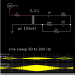
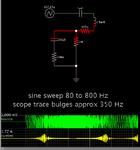
I'm doing my first transformer design, and I'm wodering what causes input current drop in attached circuit at around 300 Hz.
I know it is caused by capacitive loading, but still can't figure out what exactly is happening in the circuit.
(In the graph, the red curve represents current through primary winding and the green curve for secondary winding)

circuit.JPGcurrents.JPG

Thanks for help

dot4
 

I'm running a simulation of your secondary loop only. I apply a sine frequency sweep.

Your transformer has its secondary winding labeled as .0025, so I add a coil with value 2.5 mH. (This simulator allows me to input a Henry value in the primary, but not the secondary.)

The plot shows a sharp increase in current between 250 and 300 Hz. This may have something to do with your observations in that frequency range.

I can't be sure whether it means your primary ought to show greater current flow (as we might expect), or whether the reduced impedance has the effect of changing the time constant in the transformer, so it ends up impeding current at a certain frequency.
 

......Your transformer has its secondary winding labeled as .0025, so I add a coil with value 2.5 mH. (This simulator allows me to input a Henry value in the primary, but not the secondary.).....

Hey brad !! :) I finally installed your simulator and checked it out too. Just to let you know that the transformer model there has a primary inductance AND a turns ratio settable.
So if we know both the primary & secondary inductance values, we can find the turns ratio as SQRT(Isec/ Ipri). Hope this helps in your future simulations !!

Oh yes... doesn't the graph show current going to ZERO in primary at ~300Hz ??

cheers

- - - Updated - - -

.... I'm wodering what causes input current drop in attached circuit at around 300 Hz.
I know it is caused by capacitive loading...

Imho your output (secondary) side circuit can be simplified to just the transformer L (2.5mH) in series with the dominating elements of the 2 capacitors in series. Once you see this, you will realise that this is a simple series LC, which has a resonant freq of ~330Hz. Now being in series, at the resonance the impedance is large (infinite?), and limited only by the 1M resistor which then controls the minimum current.

Hope this helps ?
cheers!
 
Hey brad !! :) I finally installed your simulator and checked it out too. Just to let you know that the transformer model there has a primary inductance AND a turns ratio settable.
So if we know both the primary & secondary inductance values, we can find the turns ratio as SQRT(Isec/ Ipri). Hope this helps in your future simulations !!

Yes, this is helpful. Since there is no box where we can type in a Henry value for the secondary, I could instead have input a turns ratio... If I had known to look up the formula which derives one from the other.

It's a gap in my knowledge of transformer math.

Oh yes... doesn't the graph show current going to ZERO in primary at ~300Hz ??

Now I have drawn the initial schematic in the simulator, including the transformer.

Your formula above yields a turns ratio of 6.3:1 in the transformer.
.1 / .0025 = 40
Take sq. rt = 6.3.

The results agree with the OP. The scope trace shows a drop in primary current at 300 Hz. However there is no corresponding drop (or rise) in the secondary.

Since I observed the secondary by itself resonating at 300 Hz, we would naturally expect to see this reflected in the scope trace somehow.

However both sides continue to rise with frequency.

Screenshot is in the attachment:
 

Attachments

  • signal drops at 300 hz in transformer.png
    signal drops at 300 hz in transformer.png
    20.8 KB · Views: 97
  • Like
Reactions: dot4

    dot4

    Points: 2
    Helpful Answer Positive Rating
Yes, this is helpful. Since there is no box where we can type in a Henry value for the secondary, I could instead have input a turns ratio... If I had known to look up the formula which derives one from the other.

It's a gap in my knowledge of transformer math.


Now I have drawn the initial schematic in the simulator, including the transformer.

Your formula above yields a turns ratio of 6.3:1 in the transformer.
.1 / .0025 = 40
Take sq. rt = 6.3.

The results agree with the OP. The scope trace shows a drop in primary current at 300 Hz. However there is no corresponding drop (or rise) in the secondary.

Since I observed the secondary by itself resonating at 300 Hz, we would naturally expect to see this reflected in the scope trace somehow.

However both sides continue to rise with frequency.

Screenshot is in the attachment:

i suspect this is because of the nature of the LC in resonance.... !!

When a lossless LC are resonating, the currents can be very large, but there is no net gain or loss from the tank circuit. The energy simply changes hands between the inductor & capacitor. This is probably why there is NO NEED for any energy input from the primary side - and current drops very low.

The level of this current will prob'ly be determined by the non-ideality of the tank in our circuit, where the 0.37 & 0.1 & 1M resistors are also included, modified by the trafo turns ratio.

This is why the current in the pRImARY drops, but not in the secondary.

does that make sense ?
cheers!

Yes. Your explanation goes deeper than does my vague speculation in the last two lines of post #2.
 

Thank you both for answering.
Imho your output (secondary) side circuit can be simplified to just the transformer L (2.5mH) in series with the dominating elements of the 2 capacitors in series. Once you see this, you will realise that this is a simple series LC, which has a resonant freq of ~330Hz. Now being in series, at the resonance the impedance is large (infinite?), and limited only by the 1M resistor which then controls the minimum current.


Is this really true? in series resonance, the current should be maximum because the reactance parts of the impedance cancel each other out.
How do you simulate only the secondary side? I mean, where to put an voltage source.
I simulated the attached circuit with the given response.
**broken link removed****broken link removed**

Thanks
 

Imho your output (secondary) side circuit can be simplified to just the transformer L (2.5mH) in series with the dominating elements of the 2 capacitors in series. Once you see this, you will realise that this is a simple series LC, which has a resonant freq of ~330Hz. Now being in series, at the resonance the impedance is large (infinite?), and limited only by the 1M resistor which then controls the minimum current.
Or something like this. I think, the setup can be better described as a load capacitor connected in parallel to the transformer magnetizing inductance, resulting in the observed high input impedance in resonance.

Is this really true? in series resonance, the current should be maximum because the reactance parts of the impedance cancel each other out.
Yes. In fact, it's a parallel resonance setup. Transformer leakage inductance can create series resonance with capacitive load, but Ls is assumed zero in the circuit.
 

How do you simulate only the secondary side? I mean, where to put an voltage source.
I simulated the attached circuit with the given response.
**broken link removed****broken link removed**

Thanks

Sorry, your attachments brought an 'invalid attachment' error.

I drew a simulation of the secondary side alone for the reasons that:

(1) the Falstad simulator does not have an option for me to input a Henry value for the secondary winding (only for the primary),

and

(2) There was no apparent reason for the primary loop to cause the attenuation at 300 Hz.

Below is a screenshot of my simulation of the secondary loop only.

It's as simple as sending a frequency sweep through it, and measuring current.

As it turned out, there was a bulge in the scope trace around the same frequency that was causing the drop in the primary.
 

Attachments

  • LCR secondary loop reson 350 hz.png
    LCR secondary loop reson 350 hz.png
    18.6 KB · Views: 92

There was no apparent reason for the primary loop to cause the attenuation at 300 Hz.

Below is a screenshot of my simulation of the secondary loop only.

It's as simple as sending a frequency sweep through it, and measuring current.
Your simulation circuit is completely different from the original setup.

As said, the original circuit involves a parallel resonance.
 

This style better clarifies the parallel resonance structure, I think.


https://www.falstad.com/circuit/#$+...0.0+800.0+1.0+0.1 o+17+64+0+43+5.0+0.05+0+-1

imho it is irrelevant whether it is paralel or series. These two terms are only relevant when looking from OUTSIDE the LC setup.

But in this case we are not. We are directly looking at an L and a C connected to each other, and what are the currents flowing between them. That is all....

shees guys... nomenclature is irrelevant.

cheers1
 

nomenclature is irrelevant.

Yes, you can analyze the same circuit either as parallel or series resonant circuit depending on your viewpoint - how you connect to it.

The present circuit would be usually described as parallel LC, because the external terminals are connect in parallel to inductor and capacitor. I wouldn't dwell on this point if it hasn't caused some confusion in previous posts.

All in all, it's just an AC network that can be calculated.
 

Thanks for your posts.

I think I understand it now based on the resonance in the secondary circuit.

But what if we want to analyze and explain it via impedance transformation. Is it possible?
If I calculate the reactance only of the dominant 1m capacitor at 300 Hz, it is 0.53 ohm.
After impedance transformation with square of turns ratio I end up with 21 ohms.
I sense flaws in this approach :)
 

Your simulation circuit is completely different from the original setup.

As said, the original circuit involves a parallel resonance.

When I made the 'secondary loop only' simulation, it was the best progress I knew how to make at the beginning (post #2).

It showed us the resonating action at 300 Hz or so. With further discussion we have made headway past my limited understanding.

This style better clarifies the parallel resonance structure, I think.


FvM, I see you are not one whit behind the rest of us as far as skill with Falstad's simulator.

Your results match my results (post #4) of my simulation of the original setup.

I see an LC tank loop in the secondary circuit. I'm still trying to relate the discussion to what I've seen about an LC arrangement, that it can be a bandpass or a bandstop, depending on which of 4 simple ways we choose to attach it.

- - - Updated - - -

If I calculate the reactance only of the dominant 1m capacitor at 300 Hz, it is 0.53 ohm.
After impedance transformation with square of turns ratio I end up with 21 ohms.
I sense flaws in this approach :)

The 100 uF capacitor is the primary value in this loop, and it is reduced by the 1000 uF in series.

But what if we want to analyze and explain it via impedance transformation. Is it possible?

The impedance is very low at the resonant frequency.

With the transformer as a middleman, it reminds me of how a radio receiver might have a similar resonant transformer somewhere, which is tuned to respond to only one frequency.

Any other frequency going through the primary side is squelched in the secondary side.
 
  • Like
Reactions: FvM

    FvM

    Points: 2
    Helpful Answer Positive Rating
Your results match my results (post #4) of my simulation of the original setup.
Yes, that's right. My simulation setup was primarly thought as a comment to post #9, which - in my opinion - doesn't correspond to the original problem. I discovered later that you had posted the same circuit.

It's my first try with the Falstad simulator. I agree that it's useful for demonstration of simple problems like the present one, particularly the feature to embed the complete simulation circuit in a link.

But what if we want to analyze and explain it via impedance transformation. Is it possible?
If I calculate the reactance only of the dominant 1m capacitor at 300 Hz, it is 0.53 ohm.
After impedance transformation with square of turns ratio I end up with 21 ohms.
I sense flaws in this approach :)

That's basically correct, except for the dominant capacitor, which is 100 µ as Brad clarified, respectively 90 µF for the series circuit. The secondary circuit can be completely transformed to the primary, replacing the transformer with a simple inductor.


https://www.falstad.com/circuit/#$+...320+288+240+288+0 o+12+64+0+43+5.0+0.05+0+-1

In this transformed version, the parallel resonance nature of the circuit is quite obvious, I think.
 
Last edited:
...In this transformed version, the parallel resonance nature of the circuit is quite obvious, I think.

Excellent transformation....

Its is instructive to see that this behaves like the usual LC with current into the tank dropping to zero at resonance.
Also instructive is to note that the current flowing WITHIN the tank - and especially through the cap - continues to increase despite the resonance point.

Using FvM's transformation it's now easy to see why.
hope the OP actually see's this and understands...

cheers!
 
The secondary circuit can be completely transformed to the primary, replacing the transformer with a simple inductor.


In this transformed version, the parallel resonance nature of the circuit is quite obvious, I think.

I clicked the link and I've been watching this simulation operate.
Yes, it behaves like the original schematic, with fewer components.
 

Status
Not open for further replies.

Part and Inventory Search

Welcome to EDABoard.com

Sponsor

Back
Top