Continue to Site

Welcome to EDAboard.com

Welcome to our site! EDAboard.com is an international Electronics Discussion Forum focused on EDA software, circuits, schematics, books, theory, papers, asic, pld, 8051, DSP, Network, RF, Analog Design, PCB, Service Manuals... and a whole lot more! To participate you need to register. Registration is free. Click here to register now.

Transformer with air core

Status
Not open for further replies.

freedomtruth

Junior Member level 2
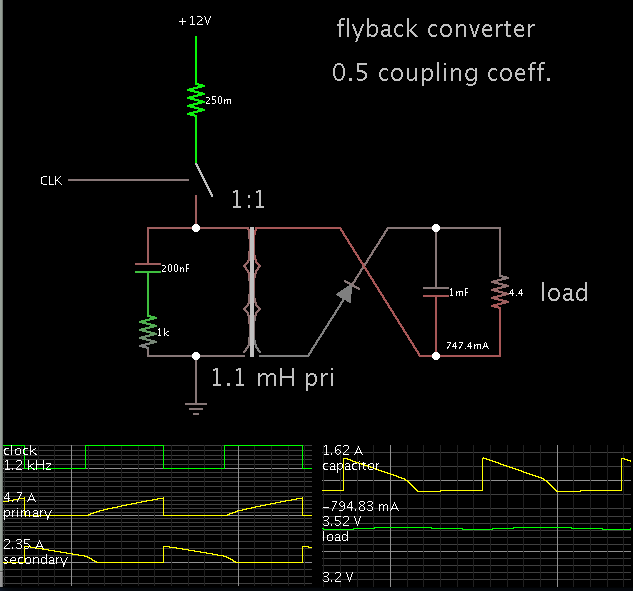
Joined
Sep 4, 2006
Messages
22
Helped
0
Reputation
0
Reaction score
0
Trophy points
1,281
Activity points
1,455
Hi
I'm trying to make a transformer with air core. It's primary is 150 turns and secondary is 180 turns. Dimensions are shown in the picture.
For the primary, I assembled the circuit in the picture and tested frequencies from 3-200 KHz.
But the best result I got in secondary was 3.3V at 8KHz with a 10 Ohm load. What can I do to increase power delivered at the secondary?
My supply voltage is 12V.

png.PNG
 

Air core transformer? i'm not sure it's really practicable. A transformer must be wounded on a core and the windings coupled together for higher power transfer between the windings.
 

Tuning the secondary coil will increase the output voltage.
 

At that frequency, you need to use a ferrite transformer so it is not a air core transformer but a ferrite core transformer
 

I presume that some totally continuous circular "air" core geometry ( e.g. Toroidal ) could minimize magnetic flux dispersion.


+++
 

I think this must be...
an experiment in wireless power transmission, right?

This may or may not help, but try a full diode bridge at the secondary. You will drop 0.6 V, but you might gain some power as you add the other half of the cycle.

As charge builds on the capacitor, you may find that less current flows through one pair of diodes.
 

I presume that some totally continuous circular "air" core geometry ( e.g. Toroidal ) could minimize magnetic flux dispersion.
The interesting transformer parameters are main inductance and coupling factor which can be also expressed as leakage inductance. Quite intuitively the coupling factor tells which part of the primary flux is shared by the secondary coil.

It's usually helpful to determine the transformer parameter by a measurement or in an EM simulation, or to derive it from engineering tables and use it in the circuit calculation.
 

If you resonate both the primary and the secondary you will increase the coupling efficiency.

How far apart are the primary and secondary?
 

It is very interesting. Hope you know that the permeability of air is 1, Normal transformer core having permeability of several thousands. The difference in permeability will be reflected.

At present you got 3.3V x 3.3V/10 ohm = 1VA
If you want to increase the power
• Increase the primary and secondary wire diameter as possible. It will increase the primary current hence increased secondary power .The frequency of operation should change.
 

Thanks guys
@shegzzyy:
This is a propeller clock project so I can't have a core.
@Fvm:
I don't know much about analog but I think you are referring to resonant circuits. I think that's not necessary because some people have done this with just a simple pwm.
@BradtheRad:
It IS a wireless power transmission but not one of those resonant circuits that you see on the net which transmit power to long distances(1+ feet). It's just a few millimeters. And BTW, diode bridge does't improve the output power.
@crutschow:
As shown in the picture, windings are 5 millimeters apart.
@smijesh:
The transformer is already built and I need help on the driving circuit. Because this transformer is proven to work and some people have got results.


I need 2.5 Watts. Is that too much?!:-D
 

I think you are referring to resonant circuits. I think that's not necessary because some people have done this with just a simple pwm.
If so, just build the circuit as other peoples did. You however asked for possible improvements and we answered it.
 

I need 2.5 Watts. Is that too much?!:-D

At 3.3 V this works out to .76 A. To get that much average current out of the secondary, it needs to have bursts of several A induced in it. To get that means you must send several amperes through the primary. Try increasing the duty cycle. The frequency can also make a difference.

You may need to move up to a full H-bridge for the primary, so that current is flowing all the time (rather than a partial duty cycle). This will require putting a full diode bridge at the secondary.

And, have you confirmed that your diode orientation is the one that yields the most power?
 

If so, just build the circuit as other peoples did. You however asked for possible improvements and we answered it.
The problem is I can't get the power other people have got with this design.
When I increase the frequency to recommended values(40-80 KHz), mosfet gets hot and secondary voltage drops to 1v.

You could still use a gapped core, which would help a lot.
Unfortunately there is no enough room for a core.

- - - Updated - - -

You may need to move up to a full H-bridge for the primary, so that current is flowing all the time (rather than a partial duty cycle). This will require putting a full diode bridge at the secondary.
I'm trying to see if I can get better results from present design. H-bridge would be my next try.

And, have you confirmed that your diode orientation is the one that yields the most power?
Yes. Actually I have tried many things including putting some random capacitors and diodes everywhere! That's how I do analog!:razz:
 

If others have gotten higher output power, how does your design differ from theirs? Why not build yours the same?

Do you know the approximate inductance of your coils?
 

If others have gotten higher output power, how does your design differ from theirs? Why not build yours the same?
I'm building the same circuit. I don't know why I can't get enough power.
Do you know the approximate inductance of your coils?
Inner coil is approximately 1.8 mH and outer coil 1.1 mH.
 

Inner coil is approximately 1.8 mH and outer coil 1.1 mH.
Did you measure it or just take other peoples claims for granted? How much is the coupling factor or the leakage inductance?

To check the parameters, the coil length and approximate winding thickness must be known too. From the picture, I would expect single layer coils.

Is it true that you are only measuring secondary DC output and have no means to determine primary or secondary AC voltage? Otherwise primary voltage would be interesting too.

Do you have a link for the previous designs you are trying to reproduce?
 

I made a simulation with your specs (approximately).

Your schematic resembles a flyback converter with loose coupling. I set the coupling coefficient at 0.5 (which could be way off, but it's only a 'guesstimate').

For a coil value of 1.1 mH, the frequency needed to be 1 or 2 kHz. If it is much faster, then current does not have time to build sufficiently during the switch-On cycle.


The .25 ohm resistor is a 'token' value to represent some amount of resistance in the first half of the cycle.

The load gets 2.5 W.
 

I would use a push-pull or totem-pole stage to drive the primary and resonate the primary and secondary. Try 3.9nF in series (not parallel) with the inner coil and 6.4nF in series with the outer coil to resonate both at about 60kHz (assuming that your inductance figures are reasonably accurate). The adjust the frequency for maximum output.
 

I was playing with the simulation for resonantly driving the primary inductor with a push-pull driver and arrived at this self-oscillating circuit below. It oscillates at the resonant frequency of the LC circuit or about 60kHz in this case, generating about 300mA pk in the coil. Not sure how well it will work in the real world but it might be worth a shot. The MOSFETS can be any that meet the current and voltage requirements. Note that R2 should be at least a 1/2W resistor.

Resonant Driver.gif
 

Status
Not open for further replies.

Similar threads

Part and Inventory Search

Welcome to EDABoard.com

Sponsor

Back
Top