Continue to Site

Welcome to EDAboard.com

Welcome to our site! EDAboard.com is an international Electronics Discussion Forum focused on EDA software, circuits, schematics, books, theory, papers, asic, pld, 8051, DSP, Network, RF, Analog Design, PCB, Service Manuals... and a whole lot more! To participate you need to register. Registration is free. Click here to register now.

Transformer 230/12V and buzzer

Status
Not open for further replies.
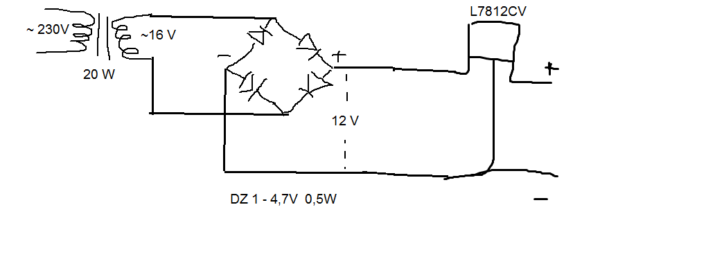
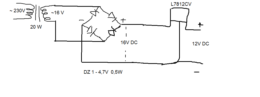
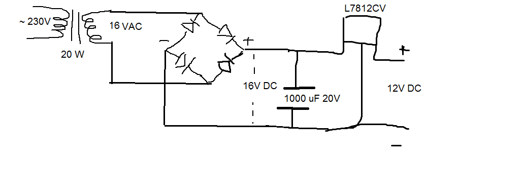
For me too there was a time when I did not understand how a 12V transformer could create a power supply of 16V.

Eventually I found out that's how high the peak of the sinewave goes.

I read a book from Radio Shack explaining how transistors work. I saw but I didn't understand.

I had to start playing with real transistors, before I could get any idea of what was going on.

I built projects from schematics. If the project worked, it meant I had followed instructions.

It took a lot of hands-on experimenting, for any of it to sink in.

Even a simple thing like a zener diode can be used in many ways.

But long explanations are too hard to follow.

Do some experimenting and enlightenment comes.
 

I want to know only information about voltage after zener diode. I have 2 programms but there aren't any zener diodes. Can you tell me that one information?
 

This simulator has a zener diode. Click the link below. The falstad.com website will open. Click Allow when asked to permit the connection.

You can alter components at will. Press ctrl (or alt) key and click on a component. An edit window will come up.

https://tinyurl.com/box2ysv

This is a screenshot:


I' m seeing you can' t help me

The buzzer voltage is NOT an exact number, and neither is your transformer voltage.

Just connect the transformer with your buzzer. It'll work fine. Since the buzzer is rated as 12v/ 5ma, then its impedance is 2400ohm.

Even if your supply goes to 16v, this will just mean a change of current upto 6.7mA. No a big deal imo.
 

No, i want to know about a zener diode. I have one C4V7 4,7V 0,5W and i don' t know about voltage which is artef that. It will be 4,7 V after diode, or 16V - 4,7V = 11,3V ?
Yes you can series a zener diode by your circuit, but as i said ago you need to reduce 2.6v of your power supply because of bridge diode voltage(0.7+0.7) till you will have 12v power supply. but i ask you if we have a effect on ac line for example ac line is 200v instead of 220 volt or 240v then your supply can regulate your voltage over 12v?
Usually zener diode use in parallel methode so it can eliminate over and under shots.
 

I have 4 diodes in bridge and this means i will have fall of voltage after that (0,7V + 0,7V + 0,7V + 0,7V) ?
 

No actually in each half cycle you have 2 "ON sate" diode.
 

Thx, is it schematic good? I have a question: after diode will be 4,7 V or 11,3V (16 - 4,7) ? Please answer that.
 

Your arrangement produces 4.7V.

By the way, the zener diode will fry. You must include a safety resistor.

The resistor will have about 10V across it.
 

can i put voltage stabilizer before zener diode L7812CV ? but where i should connect it?
 

If you use a regulator such as 7812 family then you don't need a zener diode.

However the buzzer is not fussy about its supply voltage. You need not go to the expense of using a regulator IC.

I believe a 12V buzzer should work fine on 10 to 15 VDC, unregulated.
 

some like this?
But why i need voltage stabilizer after bridge when it make voltage 12V ?

- - - Updated - - -

Sorry i ' ve mede a mistake in schematic. After bridge will be too 16 V but DC , after stabilisator wil be 12V DC i think.
 

Where you wrote a label saying 12V, you would need a filter capacitor. The value depends on how great the load is. 330 uF is reasonable for your buzzer and led.

The diodes are plain diodes. They need to be rated for minimum 23 V reverse. You have them labelled as DZ (zener), 7 V.
 

I don't need zener diode now, i have stabilizer and schematic. It is good?

THERE ISN' T A ZENER DIOD, A DESCRIPTION IS BAD (DZ)
 

You are making progress.

You still need to add a filter capacitor across the supply rails where it is labelled 16V DC.

To be correct, the transformer secondary should be labelled 12 VAC.
 

Thanks, but how much capacity i should do?
This is schematic
Can I conect + and - from that voltage source to timer 555 with all set (alarm) ?

- - - Updated - - -

And my main question: How intensity has transformer? Can i connect stabilizer and bridge for 1,5 A ?

- - - Updated - - -

I have next question about fotoresistors. I want to build alarm on timer 555. I ' ve saw videos where fotoresistors had smaller resistance when the beam of light was broken, and all set has get voltage, but when the light was detected by fotoresistor it had bigger resistance. For example : Set is plant on doorpost and laser is on the doors. When the doors will open, set will get voltage. All fotoresistors that I' ve found make it conversely. Is there some fotoresistors which i want to my alarm?

- - - Updated - - -

Some like this
 

Can I conect + and - from that voltage source to timer 555 with all set (alarm) ?

That's right.

And my main question: How intensity has transformer? Can i connect stabilizer and bridge for 1,5 A ?

Your transformer can supply enough current to power your project.

I have next question about fotoresistors. I want to build alarm on timer 555. I ' ve saw videos where fotoresistors had smaller resistance when the beam of light was broken, and all set has get voltage, but when the light was detected by fotoresistor it had bigger resistance. For example : Set is plant on doorpost and laser is on the doors. When the doors will open, set will get voltage. All fotoresistors that I' ve found make it conversely. Is there some fotoresistors which i want to my alarm?

Starting out immediately with a laser diode is risky. First try a super-bright led with a narrow beam.

Put a resistor inline to limit current through the led (or later the laser diode).

----------------------------

There are ways to invert the response of a photo-detector. Such as stacking a resistor over (or beneath) the detector, in a totem pole arrangement.

The photo-detector probably will not pass enough current to power the 555, and the buzzer, and the led's

To obtain more current (and more sensitive response), you can use a single transistor. That can power your alarm circuit.

Did you find your circuit on the internet, as a way to trigger a 555 oscillator circuit?
 

I' ve found this in the internet. Can you improve my schematic and send to me? I know about resistor before led but i' ve forgot about put it.
 

Dear kokosz,

What type of buzzer takes only 5mA at 12Vdc ? piezo electric with built in oscillator.
What is this current? 12V/5mA = 2.4mA This is adequate to turn on high brightness 5mm LED of any colour. But if you want separate controlled current no problem, just less efficient. By the way, you can power this off the line without any transformer if you asked in the first place..

Consider LED voltage drop like a battery and you are charging it, so the series resistor will depend on the voltage difference.

Now the transformer rectifier of 12Vac with a bridge and cap will produce more like 16V with no load or 1.4x 12V. with a certain amount of ripple.

So buzzer will be a little 40% louder or so and let choose RED LED resistor for 20mA for a drop of 16-1.6V= > 14.4V / 0.020A = 720Ω with power = 14.4*0.02= 288mW so choose 1/2W. Since it will be a tone frequency modulated by 50Hz/60Hz times 2 , it can be made louder and cleaner with a storage cap. if RC= 20mS then C= 0.02sec / 720 Ω or ~ 7,000uF @ 20V. (This neglects the ESR of the LED which is around 10Ω @ 20mA )

Overall it is clearly an inefficient design with large RC components, but does what you asked for.
 

I know it it inefficient but this should be a prototype. I will make clear schematic when i will know what i should do.

Why after the bridge, cap and stabilizer there will be 16V ? Stabilizer doesn' t make 12V DC ??
How i can make 12V DC ??
Please correct my schematic
 

Status
Not open for further replies.

Part and Inventory Search

Welcome to EDABoard.com

Sponsor

Back
Top