Continue to Site

Welcome to EDAboard.com

Welcome to our site! EDAboard.com is an international Electronics Discussion Forum focused on EDA software, circuits, schematics, books, theory, papers, asic, pld, 8051, DSP, Network, RF, Analog Design, PCB, Service Manuals... and a whole lot more! To participate you need to register. Registration is free. Click here to register now.

Tracking A/D converter

Status
Not open for further replies.

zionico90

Member level 2
Joined
Nov 28, 2013
Messages
48
Helped
0
Reputation
0
Reaction score
0
Trophy points
6
Activity points
369
Hi guys,

i should design a tracking A/D converter based on R-2R ladder network driven by CD4029 digital counter; the analog input range must span from 0V up to +5V.
I have already design the DAC but I have still some problem with the whole circuit. The circuit basically includes:

- DAC Block: 2-2R ladder network+inverting amplifier to obtain the dynamic range 0-5V
- Comparator Block by using a simple op-amp
- Digital counter

The LTSpice circuit schematic is in annex.
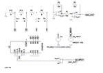
tracking.png

Why the circuit is not working? I have the impression that some connections is wrong. Moreover, I would like to know where I have to physically do the check in order to verify how the ADC follows a sinusoidal analog input.

Thank you for your help hoping that this section is correct!
Marco
 

The circuit can surely not "work" because it's incomplete (missing resistor values and OP power supply), unreasonable simulation time duration.

If you are unsure about the circuit parameters, try tracking a slow varying input voltage. You should also consider that the circuit can only track a voltage inside the DAC range, surely not a bipolar sine. Rethink the test setup.
 

Thanks guys for your answers. The circuit was just an idea and so didn't include resistor values but you are right, it is better to speak looking at the complete circuit below. I attach also the asc file.

**broken link removed**


Thank you very much for your help!
 

Attachments

  • Tracking ADC.zip
    1.5 KB · Views: 36
  • Schermata 2017-05-31 alle 23.01.55.png
    Schermata 2017-05-31 alle 23.01.55.png
    78.9 KB · Views: 65

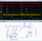
Here is you circuit modified to work.
I didn't try to optimize it, just changed it enough so that it was working.

The voltages were changed and the comparator negative voltage was connected to common so that the comparator output is compatible with the CMOS 0-5V input.
The clock frequency and simulation time were changed to be compatible with the 100Hz signal frequency (the circuit can't operate with only 1 clock pulse per analog signal cycle).
The gain of U2 was reduced slightly so that all four bits are used for better resolution of the digital output.

Capture.PNG
 
Last edited:

Thank you very much for the help!
I have a last question: are the transimpedance and the inverting amplifier connected to the R-2R ladder network necessary in this circuit? I saw a circuit in which the output of the R-2R was directly connected to the comparator.

Thanks!
 

R-2R ladder can be operated with voltage output.
 

Status
Not open for further replies.

Similar threads

Part and Inventory Search

Welcome to EDABoard.com

Sponsor

Back
Top