zionico90
Member level 2
Hi guys,
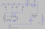
i should design a tracking A/D converter based on R-2R ladder network driven by CD4029 digital counter; the analog input range must span from 0V up to +5V.
I have already design the DAC but I have still some problem with the whole circuit. The circuit basically includes:
- DAC Block: 2-2R ladder network+inverting amplifier to obtain the dynamic range 0-5V
- Comparator Block by using a simple op-amp
- Digital counter
The LTSpice circuit schematic is in annex.

Why the circuit is not working? I have the impression that some connections is wrong. Moreover, I would like to know where I have to physically do the check in order to verify how the ADC follows a sinusoidal analog input.
Thank you for your help hoping that this section is correct!
Marco
i should design a tracking A/D converter based on R-2R ladder network driven by CD4029 digital counter; the analog input range must span from 0V up to +5V.
I have already design the DAC but I have still some problem with the whole circuit. The circuit basically includes:
- DAC Block: 2-2R ladder network+inverting amplifier to obtain the dynamic range 0-5V
- Comparator Block by using a simple op-amp
- Digital counter
The LTSpice circuit schematic is in annex.
Why the circuit is not working? I have the impression that some connections is wrong. Moreover, I would like to know where I have to physically do the check in order to verify how the ADC follows a sinusoidal analog input.
Thank you for your help hoping that this section is correct!
Marco