Continue to Site

Welcome to EDAboard.com

Welcome to our site! EDAboard.com is an international Electronics Discussion Forum focused on EDA software, circuits, schematics, books, theory, papers, asic, pld, 8051, DSP, Network, RF, Analog Design, PCB, Service Manuals... and a whole lot more! To participate you need to register. Registration is free. Click here to register now.

to detect incoming low amplitude sine signal

Status
Not open for further replies.

manissri

Full Member level 5
Joined
Apr 16, 2005
Messages
281
Helped
9
Reputation
18
Reaction score
3
Trophy points
1,298
Activity points
3,279
Hi am having query
i have one input signal of approx 0.1v with frequecy around 10-800KHz
we want to detect that input signal at output by using some digital control and with another electrical signal
as measurement reference ( a sine wave aprox 0.5v with freq of 500KHz)
the how to detect the input sine wave by using some digital control and reference sine wave

what circuit I can use to detect the input sine wave at my output
 

Is input signal accompanied by appreciable noise ?

Do not understand the need for the ref signal ?

Once you detect the signal what do you do with the presence of that signal ?


Regards, Dana.
 

Is input signal accompanied by appreciable noise ?

Do not understand the need for the ref signal ?

Once you detect the signal what do you do with the presence of that signal ?


Regards, Dana.
HI Dana
Actually some how we need to detect the input signal by using these referene or any other ref we can use but we have to detect that at output of detector ckt we care getting input sinewave . for example we use comparator to detect some signals by using a dc ref when the signal goes high then comp output goes high and vice versa
 

Sig varies over a wider Freq range. How much latency from the time it falls
into the range 10 Khz to 800 Khz to detection can you tolerate ?

A simple freq cntr solution with code can solve this. And an amp to get
signal into logic levels range.


Regards, Dana
 

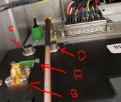
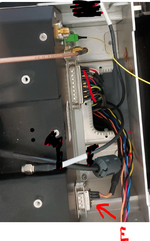
On the OCT device on the pictures we have an optical input, we expect an electrical output (Measuring an RF signal ~0.1V with frequencies around 10-800 kHz), a power supply (+-12V), maybe some digital control and maybe another electrical signal as a measurement reference (a SINE wave ~0.5V with frequency 500kHz).
how to find the signals can you help me ?
 

Attachments

  • image002.png
    image002.png
    401.2 KB · Views: 105
  • image001.png
    image001.png
    548.2 KB · Views: 94

Actually some how we need to detect the input signal by using these reference or any other ref we can use but we have to detect that at output of detector ckt we care getting input sinewave
Far from an actual specification, unfortunately.

The role of the 500k reference is still unclear. Is there an yet untold relation to the input signal, e.g. a set of fractional frequency ratios? "care getting input sine wave" also needs explanation. Should we read it as spectral criterion? If so, does it actually address signal waveform or stationary fundamental frequency, which can be e.g. met by a 10 kHz square wave?
 

Status
Not open for further replies.

Similar threads

Part and Inventory Search

Welcome to EDABoard.com

Sponsor

Back
Top