Welcome to our site! EDAboard.com is an international Electronics Discussion Forum focused on EDA software, circuits, schematics, books, theory, papers, asic, pld, 8051, DSP, Network, RF, Analog Design, PCB, Service Manuals... and a whole lot more! To participate you need to register. Registration is free. Click here to register now.
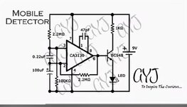
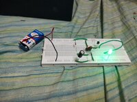
I have implemented this activated mobile detector circuit on breadboard but my LED is glowing continuously when connected to battery. Can anyone help me to resolve it.
But a "mobile detector" needs to be sensitive in the GHz range. Breadboard is not suitable for this frequency range.
All in all this is an extremely simplified and thus unreliable (to avoid the word: "crappy") solution. There is no antenna, no reciever part, no filter, the CA3130 is not suitbale for GHz, even the LED control is designed badly.
Best way is to contact the original designer. (Indeed I would be surprised if he/she is available for support. Since support for a bad design is rather time consuming)
My honest opinion (you are free to agree/disagree/follow .. or not): forget about this circuit. It´s a waste of time.
Breadboard circuit has differences to schematic, different resistor values, different connections. The "mobile detector" is extremely simple, as stated but can work if the schematic is correctly implemented.
This site uses cookies to help personalise content, tailor your experience and to keep you logged in if you register.
By continuing to use this site, you are consenting to our use of cookies.