Continue to Site

Welcome to EDAboard.com

Welcome to our site! EDAboard.com is an international Electronics Discussion Forum focused on EDA software, circuits, schematics, books, theory, papers, asic, pld, 8051, DSP, Network, RF, Analog Design, PCB, Service Manuals... and a whole lot more! To participate you need to register. Registration is free. Click here to register now.

TIP31 feeding about 25 leds (audiorhytm circuit)

Status
Not open for further replies.
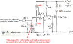
Just a word of caution: if the output of the amplifier is connected as a bridge, it means both speaker wires are driven. The schematic I gave will still work if driven from the pre-amplifier stages but if you drive it from the loudspeaker wires, make sure the ground of the power source is isolated. If you do not, it would short one of the speaker wires to ground and possibly damage the amplifier. It is doubly important if you try to drive it from the loudspeaker wires from two channels.

The alternative is to use a small audio isolating transformer at the signal input so the loudspeaker wires have no direct connection to anything else.

As I stated, if you connect it to the pre-amplifier output (before the volume control) it will still work as it is.

Brian.

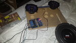
The first tests have began, hey this thing is nice! I am feeding it with 24v with the 8.3A source. So far I have noticed that loudspeakers are loud and they don't give any bass response, which means that board already has a mid filter some there (loudspeakers don't have it, just at the tweeters).

8" subwoofer has performed good movements, which tell me that maybe it would be not necessary putting it into 2 ohms, still cannot conclude too much about the sub, because it sounds ugly without the enclosure, will try to build a simple ported enclosure just to properly test it soon, and not waiting until having the final enclosure with lots of things.

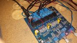
Heatsinks barely get warm, as I mentioned, I still need the enclosure to test it with a proper load and read temps. The sound is cristal clear, not any undesired noise with or without music on.

Do you still recommend me connecting the comparator on the loud speakers? those terminals don't have bass frequencies, if you tell me that really is not possible connecting them directly on the subwoofer output, then I can try finding a point after the amp and before the mid filter, so there I can connect the comparator, which is less easier that the subwoofer output, anyway will need a lot to solder, and as I mentioned, I maybe will wire some RCA so I can feed from that way as well.

So far I am happy with this thing, a good power supply helps a lot (which seems I have it), will read the power consumption once I have at least the sub mounted on its enclosure.
 

Attachments

  • 20160730_200059.jpg
    20160730_200059.jpg
    911.3 KB · Views: 51

Omg, can not edit!

I just found that a pair of coils are getting hot, not sure how dangerous, but they are even hotter than the subwoofer heatsink, which works fresh, barely warm.

Is it normal for those coils to getting hot? I mean, they are Not very hot, but put me to worry about that, are these coils designed to work on high temperature? repeat, they are not very hot, but compared to the other ones, are hotter, and not precisely warm, a little hot. I definitely will put a little fan to fresh all components, even the ones of power supply, not sure if convenient putting all the hot devices inside a little plastic enclosure with a little fan, so this box will be in the subwoofer chamber, which is ported and will always have fresh air because air exchange, mayme not need for the plastic enclosure and fan, not sure if subwoofer ir exchange will fresh everything inside by itself.

131145d1469948844-20160730_235716.jpg


By the way, loud speakers do show some bass activity after all, so I supposed I will connect there the comparator, which already has the low pass filter.
 

Attachments

  • 20160730_235716.jpg
    20160730_235716.jpg
    989.1 KB · Views: 69
Last edited:

This looks like a class D amplifier (I can't access the data sheets at the moment) so the coils are likely to be the output filters. It is normal for them to run warm, it is due to the losses in the ferrite material they are made of. Think of it this way: If high frequency goes in from the output stage and it doesn't come out at the loudspeakers, it has has to go somewhere else! By high frequency here I mean the class D switching frequency, not high notes in the audio.

As I mentioned, it looks like BOTH loudspeaker wires are driven (bridge configuration) so there is no 'ground and live' side to the wires and if you connect either one to ground through some other circuitry you will short out part of the amplifier, probably with bad consequences.

Class D is efficient but you still need to keep it cool, completely enclosing it is a bad idea, natural air flow is probably OK but keep an eye on it and make sure there is a path for the air to flow in to and out of the housing. Remember hot air is less dense so ideally you want the air inlet below the amplifier and the outlet above it so it creates it's own convection. It id gets too hot to touch, I would suggest you force cool it with a small fan.

Brian.
 

In post #112 I explained that the peak voltage at one subwoofer speaker wire is only about 10V. Also the comparator circuit has a voltage divider at its input so the maximum peak input to the LM311 comparator is only 5V which is .... OOPs, the negative swing of the AC audio input will swing below ground and destroy the input of the LM311 since it does not have a negative power supply voltage shown on its datasheet.

A simple fix is to remove the input capacitor of the LM311 circuit so that when the output from the amplifier swings from +2V to +22V then the input of the LM311 swings from +1V to +11V which is fine if its supply is +11V or more. Like this:
 

Attachments

  • comparator circuit.png
    comparator circuit.png
    92.3 KB · Views: 62

@Betwidx: I think board has 2 class D amplifiers, each one is stereo, but one of them is bridged, so one is for the .1 channel for subwoofer. So no no no, only bass wires are bridged, loudspeakers are driven by one chip which is not btl or bridged. :( So after all this circuit is not suitable for big almost like maybe 100w? or only from speaker wires which are in btl config?

So now you know this about the 2 chips, then its more proper connecting the input of the comparator to the output of the chip which is not in bridge mode? (I should connect both channels just as your suggested dual comparator input, just in case one bass pattern onlys showed in one channel).

#Audioguru, Oh man! now I am so confused... is not it enough in that case by just increase the resistor input to a higher value? for example 200k? I do not think it should be a good idea to remove that 100nf, otherwise the leds will respond to higher frequencies than that value is filtering.

Should that LM311 has a dedicated and separated little power supply then? which would be like, hey, I already have more than enough power supply, this should not be good idea, but necessary after all?

If the problem is that big, but its ok wiring the LM311 just after a preamp, then I will go with that method of input source, which I dont like it. Unless you tell me that with your modification will be suitable for the subwoofer output.
 
Last edited:

Absolutely NOT!!
Never mind what ebay says or does not say since they know NOTHING about electronics.
The Texas Instruments datasheet for the TPA3116 IC shows that it is a stereo (2 channels) class-D amplifier. Each of its two channels is bridged (BTL).
The Chinese amplifier might or might not use TI ICs. One IC is used for stereo left and right mids and highs and a second IC has its two channels paralleled (PBTL) for the subwoofer (lows).
I assume that the Chinese amplifier has a crossover network and mixes left and right to feed the subwoofer amplifier. But ebay provides no details.

One channel of the IC produces about 60W at clipping into 4 ohms with a 24V power supply. Both channels paralleled produces a little less than 120W into 2 ohms.

The LM311 will work fine in my modified circuit when powered from the same 24V supply as the amplifier. It must never have its input voltage less than its negative power supply voltage (but there is no negative supply, it is ground instead) so I fixed it with the changes I made so that it can be connected to one output wire of the subwoofer amplifier.
Similar but different corrections must be made if the LM311 circuit is connected just after a preamp.

You can try it with and without the 100nF filter. The series input capacitor MUST be removed (as I showed) if it connects to the output of the subwoofer amplifier.
 

Absolutely NOT!!

Oh ok will try that, and that's supposed to work in a range of X watts to X watts? I mentioned that also have plans to test it in more than 500w subwoofer, in that case should I do modifications?
 

The LM311 IC will blow up if it is connected to the output of the subwoofer amplifier without my modifications. If you have the trimmer resistor set so that it works well at high volume then it will not work if the level drops or if the volume control is turned down. It is too bad you do not have a schematic and parts layout to find a connection spot before the volume control.

An amplifier (will be 500W?) has an output voltage determined by whether it is bridged or not and by its speaker impedance. Is it bridged? What is the speaker impedance for 500W? Is it real Watts or is it fake Whats?
 

i am so tired of all this, will see to connect it after some located pre amp on board some there, or add own mine, enough powerful to also feed several devices as spectrum analyzers, EQ, etc, but definitely won't connect it through speaker wire, anyway it was like unusual doing that.
 

Johanx2, don't give up - it is confusing, especially if you don't come from an electronics background. Sadly, when it comes to specifications, most sellers, especially ones on ebay, tend to be 'creative' rather than scientific. Often the figures they give are either to blind you with science or plain lies. It's quite common to see amplifiers that claim to produce more output than is theoritically possible, drawing less in than they produce out, or ones using device XYZ123 that it's manufacturers claims is a 1W amplifier but the seller claims is a 10W amplifier. It's only when you forget the claims and look at the design itself that you uncover the truth.

I sense you do not understand what a bridge amplifier is and the consequences of wiring it wrongly, so I'll try to explain in laymans terms:

A "single ended" amplifier has an output stage that produces a voltage between it's positive and negative supply lines. The loudpeaker connects between the output and ground. It follows that the voltage across the loudspeaker is anchored at zero on one side and the other can at most reach the extent of the power supply voltage. In some cases, the amplifier only has one supply, in some cases it has a positive and negative supply. For example, an amplifier running from a single 24V supply like you have can only produce at most 24V across the loudspeaker wires. Practically speaking, because of the way circuits work, it would be quite a lot less.

A "bridged" amplifier works in exactly the same way except two amplifiers are used to drive one loudpeaker output. The loudspeaker is connected between the outputs of the amplifiers (hence the warning about shorting them to ground!). When the audio is fed to the amplifiers, one gets the signal as it is, the other goes through an extra circuit that turns the waveform upside down (inverts it). The two amplifiers are carrying identical signals except for being mirror images of each other. This time, instead of one speaker wire being ground, both are driven in opposite directions and therefore it is possible to double the voltage across the speaker wires. Because power is voltage squared divided by the load resistance, you get more effective power out.

Example maximum speaker voltage (I'm calling the speaker wires A and B):
single ended - 'A' end is always zero, 'B' can be between zero and 24V so maximum across the wires is 24V
bridged - 'A' end can be at zero while 'B' can be at 24V and also 'B' can be at zero while 'A' is at 24V so maximum across the wires can be 48V. If you connected a meter across the wires it would go from -24V to +24V so effectively you have 48V available.

Brian.
 
Thanks Bet for the data. On ther other hand, I have been thinking in the design that showed, which is a rectangle with two separated chambers, one is small and its for the loudspeakers, and the other one for the subwoofer.

In the past, I had a panasonic sound system, the enclosure was lie all the space was for the sub, and in front it has a fancy cover that places the loud speaker of a size about 6" , I remember that at its back, it had little plastic chamber, with no hole at all. So this speaker was some kind of isolated from everything, it had a mid high filter, so it showed no bass response at all.

I am planning doing something similar with my loud speakers, and give more space for subwoofer driver, I also will to play with a 3" abs pipe that I bought, it was impossible finding a 2.5" ID, but realize it was ok a 3", just will need to play with the length, and all this make it convenient for a little more space to whole piece.

For isolating the loud speakers, will need to cut some rings, 3/4 thick, and glue some layers until I reach the magnet and can put the final piece, which is a wood circle, so all this is supposed to be isolated from subwoofer activity, so will treat sections (for example with harsh sand paper) before gluing, so nothing will take off. Will put couple of screws on each domo cover, so no air can came in through.

Would you recommend this? at what filter should be recommendable for not passing the low frequencies? the loud speakers will barely get space, almost nothing, so I don't think it would be good idea letting it pass the medium bass response this loudspeakers can get.
 

The speaker for the mid frequencies and the tweeter should have solid enclosures. If their enclosures are inside the enclosure for the subwoofer then the resonant frequency of the subwoofer and its enclosure might be increased too high because then its enclosure will be too small. The size of the enclosures for the mid frequency speaker and the tweeter also affect their resonant frequency. The tweeter probably has a sealed back as its enclosure.
Quote: "the loud speakers will barely get space, almost nothing" then the lower mid frequencies will not be heard because the resonant frequency of the mid frequency speaker will be increased too high. The speaker is supposed to have an enclosure that is suitable for it.

Why are you talking about filters? The amplifier is supposed to already have filters on it. But it is cheap and it is Chinese so there are no details about it.
 

I have a sense,,the OP lacks necessary design fundamental pre-requisites to make a quality system and we'll still be chatting about Chinese amplifiers and ineffective LEDs.

The self resonant frequency SRF of unloaded speaker bass can be tuned lower only with a large air volume on the cone. Bass Reflex 101 aka Helmholtz Resonator. There are alternatives which use sub-woofers.

Measuring The SRF is a pre-requisite on a scope or recording device.

A crossover filter design is necessary. and phase coherence is important.
 

I am actually playing with data obtained from a Helmholtz-Resonator calculator, this because had problems finding a 2.5" diameter pipe, so I will play with a 3" ID ABS pipe, I am making an enclosure of 1-cF in order to play with different pipe lengths and see how does the 8" pyle sounds. The pipe I have is 3"ID by 24", do you recommend me to first use all that length?
 

Your port tube is much too long. Maybe your resonator program is for a tube that has one end closed, not for a speaker vent.

I looked on Pyle's website and found an 8" "Premium" subwoofer speaker rated at 500 Whats. It looks cheap. They provide no detailed spec's. They say its frequency response is 55Hz to 6kHz but do not say the important enclosure type, size and +-dB variation. 55Hz is not a subwoofer cutoff frequency anyway and might be at -12dB.

I have an unusable speaker enclosure design program but it does not work on my Windows 10.

Here is a typical half-decent Scanspeak 8" woofer that also does not have detailed spec's but they show details for 3 enclosures. A 1.5 cubic foot enclosure has a port tube that is 2" diameter and is 5" long. The resulting low end -3dB cutoff frequency is 42Hz.
 

Attachments

  • 8 inch woofer spec's.png
    8 inch woofer spec's.png
    101 KB · Views: 52

Your port tube is much too long. Maybe your resonator program is for a tube that has one end closed, not for a speaker vent.

I looked on Pyle's website and found an 8" "Premium" subwoofer speaker rated at 500 Whats. It looks cheap. They provide no detailed spec's. They say its frequency response is 55Hz to 6kHz but do not say the important enclosure type, size and +-dB variation. 55Hz is not a subwoofer cutoff frequency anyway and might be at -12dB.

I have an unusable speaker enclosure design program but it does not work on my Windows 10.

Here is a typical half-decent Scanspeak 8" woofer that also does not have detailed spec's but they show details for 3 enclosures. A 1.5 cubic foot enclosure has a port tube that is 2" diameter and is 5" long. The resulting low end -3dB cutoff frequency is 42Hz.

AG can you send me the program. THis is an excellent little speaker. Notice that the free resonant f= 30Hz and all 3 designs raise the resonant frequency, so one can imagine that a significantly larger box is needed to extend the bass with a resonance below 30 Hz and stay away from the same f.
 

AG can you send me the program.
It is called Boxplot and it was free but today it costs $25.00US +sh and h. There is a shareware version today that has a free demo: https://www.diamondcut.com/boxplot.htm


THis is an excellent little speaker. Notice that the free resonant f= 30Hz and all 3 designs raise the resonant frequency, so one can imagine that a significantly larger box is needed to extend the bass with a resonance below 30 Hz and stay away from the same f.
I think in a huge enclosure (infinite baffle?) it will reach its maximum excursion limits when playing 20Hz to 30Hz at a fairly low power.
 

Well, Helmholtz-Resonator calculator told me that can down A LOT the hz, to set the enclosure around 25 hz if I use that 3" pipe, 24" long, and keep the enclosure size about one cubic foot, I would put a little more space, about 1.5 3F, the thing is that, yeah, that pipe is very long. Do you think it may sound good? or will I discover it once have everything done and built? I am making something just to test this, hope to get good results.
 

The resonator calculator is completely wrong to make a vented speaker enclosure.
The enclosure must match the spec's of the speaker. Which 8" Pyle speaker is it, the one rated at 500W with a 55Hz free air resonance? Then an enclosure design will never have a cutoff below 55Hz.
 

It is called Boxplot and it was free but today it costs $25.00US +sh and h. There is a shareware version today that has a free demo: https://www.diamondcut.com/boxplot.htm


I think in a huge enclosure (infinite baffle?) it will reach its maximum excursion limits when playing 20Hz to 30Hz at a fairly low power.


aha 16 bit program. only good for 32 bit windows
 

Status
Not open for further replies.

Part and Inventory Search

Welcome to EDABoard.com

Sponsor

Back
Top