Continue to Site

Welcome to EDAboard.com

Welcome to our site! EDAboard.com is an international Electronics Discussion Forum focused on EDA software, circuits, schematics, books, theory, papers, asic, pld, 8051, DSP, Network, RF, Analog Design, PCB, Service Manuals... and a whole lot more! To participate you need to register. Registration is free. Click here to register now.

TIMER1 RTC, oscillator accuracy problem, PLEASE HELP.

Status
Not open for further replies.
Hi,

They are as close to the pcb as you can get which is good, though smd for early development work can make things difficult.

Cannot see any signs of your 20mhz crystal which should also be close to the pic ..? -any reason you are not using the 8mhz internal oscillator ?

Crystals are said to be delicate things, though I have not have any problems soldering them.

Always use the Count to Three seconds as you are soldering, if the joint is not complete by then, stop and let the component cool before reworking.

Being as that bit of code I posted works fine on my 16F, running in front of me now, you really should try it on yours as it should prove where the problem is.

The 20 Mhz crystal is located on the other side of the board but close to the controller.
I build all 3 PCB for testing purpose I put a crystal on each one , and initially I wanted to make a RTC without 32768 crystal, just using the 20 Mhz crystal, but was not accurate enough , then I decided to try using the 32 crystal, it seems both oscillators are not good enough.
I run you code about 1 hour and it drifted , I cannot say yet how much almost 1 second but it is clearly visible.
I think I need to improve the oscillator, I also cleaned the boards very well with alcohol and it seems now I have 1 second in 3 hours, better than yesterday evening.
Maybe I need to play with the capacitors value.
Datasheet says 33pf, but in another place I found a formula to calculate the capacitors value and for the crystal I use , I should have about 8pf capacitors....
 

Hi,

Ok, so checking the Timer1 Flag has improved things, but is the timer one second fast or one second slow in the 3 hours ?

I run on 22pf, if I remember correctly 33pf will make it run slower....

You could try 27, 22, or 15 pf and see how that affects things.

What accuracy are you aiming for ? 1 second a day, 1 second a week ?

Don't forget that if you establish a sound design but its still slightly out, you can always make a software adjuster to compensate for the error rate.

Seem devices like the DS1307 RTC use a 32k crystal with 12.5pf internal caps, but they just say accuaracy is down to the crystal used and pcb layout - see their datasheet.

I have 2 devices running 24/7 with a 32k Timer1 ISR RTC so will check their times /accuracy overnight and let you know the results
 

There are many sources of possible error. Having designed many time and frequency stability designs since the mid-70's, I can ony offer some advice based on my experience.

Get a hardware based time reference to measure clock accuracy in real-time. Having a reliable counter or time base is critical to isolating sources of error or drift.

YOu can buy purchase or make a 1ppm or better TCXO that is stable and then mix using PLLs to compare at the same frequency. If you prefer an analog display, I one used a sawtooth signal generated by from a square wave to sample by the edge of the signal under test. The result is a ramp which changes slow with frequency error and then repeats exactly the same shape as the sawtooth it is sampling. Then determine what causes error in the RTC.. V+ sensitivity test for load variance, time variance, temp variance and mechanical shock, vibration

Then figure how to deal with the variances by filtering, isolation, regulation.

Next analyze the software analyzer for sources of measurement error.
Missing sample, extra sample due to lack of real time control in polling or IRQ response time on edges of clock pulse. If reading a digital value from RTC, then this is ok but pulse counter designs need to consider ingress noise from long wires and lack of shielding and missing counts in software due to background tasks.

I used to generate clocks with 1e-10 stability tested to aerospace environmental limits for doppler track of sounding rockets and also data separators for 4Mbps data in vertical blanking intervals of TV signals as well as many other applications.

32KHz clock chips today are very good mechanical oscillators, but for more reliability higher Q ceramic and even higher Q Xtal sources are better. < 1 uW is possible in RTC clocks.

- - - Updated - - -

if you can afford this **broken link removed**, it has very good specs. It is similar to the Vectron OCXO clocks I used in the 70's with similar specs (for benign env.) using a specially cut xtal called the SC mode vs the AT mode of cuts. These have much higher Q values for resonance the 50 cent 32KHz clock.

This product is only for those who need ultraminiature, rugged, ultra-low power where prices start at $1500 !!


**broken link removed**

They also have an **broken link removed** on many time correction methods.

**broken link removed**

You can also use the 1pps or 10Mhz clock from any GPS to feed a cheap counter with ext ref. input with 10Mhz to measure your 32KHz.
Note that you can get 32KHz clocks in 3 types, Tuning fork, ceramic and crystal osc. So take note which one you have. They may vary form 2 to 8 ppm..

Now for the miniature Vectron clocks smaller than the ones I used 36 yrs ago but around the same price $331 today.

Connect it to a cheap frequency counter for more accurate readings. NOTE that the Mouser catalog online has 100ppm.. It is actually 200ppb or parts per billion per month.
initial tolerance (df/f0) -500 to 500 ppb @Vc = 2.5 V; 25 °C
vs. supply voltage change (df/f) -20 to 20 ppb static; 5 V ±5 %
vs. load change (df/f) -20 to 20 ppb static; Load ± 10 %
vs. aging / daily (df/f) <± 10 ppb after 30 days ; @ 25 °C
vs. aging / month (df/f) <± 200 ppb after 30 days ; @ 25 °C
vs. aging / year (df/f) <± 500 ppb after 30 days ; @ 25 °C
vs. aging / 10 years (df/f) <± 3 ppm after 30 days ; @ 25 °C
C4400.jpg


Now for a cheaper frequency reference;
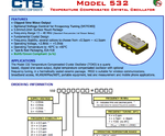
This clock starts $3.5 with 2.5ppm but ? aging depends on p/n and price.
Screen shot 2012-07-26 at 8.16.38 PM.png

I hope this helps.. free help takes time.
 
Last edited:
Hi SunSkyGuy,

Interesting stuff, though not sure Wasilus would want to spend $1500 on a reference device ! :lol:
 

Frequency calibrated at 25°C. OSCTUNE register can be used to compensate for temperature drift.
The 16f88 datasheet suggest using an external temperature sensor and a lookup table of temperature-to-oscTune values to get "an accurate RTC" from the 16f88...
In the PIC24, the RTC has a "tuning value" that is how-many-ticks-per-minute to add or subract from the timer value, and tends to keep decent time just from it's internal FRC/32khz TMR1sourceMode...

There's small PIC24's, worth a look
NEAL
 

Hi,

I have 2 devices running 24/7 with a 32k Timer1 ISR RTC so will check their times /accuracy overnight and let you know the results

Hi,

My 2 units are built using a standard watch crystal and I did not do anything to them, hardware or software , to 'tune' their timings; actually never checked their accuaracy at all, as it was a proven design.

Over 15 hours both units gave differences of well under 1 sec against my stopwatch, would not really expect a simple diy circuit to improve on that.

Have you tried the full Zero Error 1second Clock code from RB - does it work ?
 

Hi,

Ok, so checking the Timer1 Flag has improved things, but is the timer one second fast or one second slow in the 3 hours ?

I run on 22pf, if I remember correctly 33pf will make it run slower....

You could try 27, 22, or 15 pf and see how that affects things.

What accuracy are you aiming for ? 1 second a day, 1 second a week ?

Don't forget that if you establish a sound design but its still slightly out, you can always make a software adjuster to compensate for the error rate.

Seem devices like the DS1307 RTC use a 32k crystal with 12.5pf internal caps, but they just say accuaracy is down to the crystal used and pcb layout - see their datasheet.

I have 2 devices running 24/7 with a 32k Timer1 ISR RTC so will check their times /accuracy overnight and let you know the results

One of my boards have 22pf capacitors the other 33pf , all 3 boards in previous tests run slower .

I am aiming to about 1 second in 2 days.
Yes I know i can compensate the error rate, but first I need to have the oscillator stabile.

Now I made some changes, I put a resistor of 220K in series at the T1OSO and a 22pf capacitor, and on T1OSI I put a 13pf capacitor, now this board is running faster but more accurate, it is 0.5 seconds in 4 hours, the crystal specs unknown.
The same I did to another board but a different crystal, but this one is slower about 0.3 seconds in 1 and half hour, the crystal here has 6pf Load capacitance.
The first one is running on battery and the last one on power source. I need to test if the power source has some negative effect.
 

You need a counter to measure instantaneous error or a phase detector and some reference clock that is much more stable. !!

Best test some called a Schmoo plot back in the 80's for some reason.. Vary Temperature vs voltage +/- and measure error.

Also what P/N are you using. Is it crystal or Tuning fork type? Do you have adequate filter on Vdd supply and shielding to prevent errors? I suggest you find a stable reference freq to compare. Many sources are broadcast if you can tune a cheap stable 1ppm TCXO. then using counters or PLL compare phase error drift within 1 second

They all have supply sensitivity and temp sensitivity to some degree but it is possible to correct.

Answers pls?

Well I just want a simple RTC, about 1 second at 2 days accuracy is enough, I do not have sophisticated measurement instruments , I canot afford to spend a lot of money to buy some very accurate reference clock.
The datasheet of one crystal that I am using says ( MS1V-T1K Tuning Fork Crystal), the other one I've tried KDSO 750, no datasheet available, unknown parameters.
85SMX CRYSTAL as well available.

Power suply is from a 7805 stabilizer and 200 mf capacitor, no shielding , the power source is far away from the board.

- - - Updated - - -

I just found out that the boards behave the same on battery and stabilized power supply, it means the power supply does not have a negative effect on oscillator.
Also on the board that runs slow I changed the crystal leaving the same capacitors, and with the new crystal is running faster now. So I suppose I still need to play with the capacitors value.
 

hello,

As wp100 said, the best way, is to use interrupt with timer1, to
be sure to catch the timer overflow at the front edge of timer overflow not at the level of bit 7.
because bit 7 of TMR1H is set beetween F0 value and FF value !
so error can be very big ! => big aleas of detection
You need to test TMR1 interupt flag , not TMR1H ...
even you don't use interrupt


in your 16F88 program
what does
movf TMR1H,W ;?????
in the pool check ?
 

I offered this 2.5ppm $3.50 solution for you in post 24... to measure short term errors adding a 1pps software counter with hardware output. To compare use cheap BCD CMOS counters to scale down to 1pps or any common other method.

I suggest you purchase this while you review the above code suggestions for errors.
77757d1343348328t-screen-shot-2012-07-26-8.16.38-pm.png
 

hello,

As wp100 said, the best way, is to use interrupt with timer1, to
be sure to catch the timer overflow at the front edge of timer overflow not at the level of bit 7.
because bit 7 of TMR1H is set beetween F0 value and FF value !
so error can be very big ! => big aleas of detection
You need to test TMR1 interupt flag , not TMR1H ...
even you don't use interrupt


in your 16F88 program
what does
movf TMR1H,W ;?????
in the pool check ?


The method of testing bit 7 of TMR1H is from Roman Black zero errors RTC routine and should work as other people have tested it.

I already tested the circuit with TMR1 interrupt flag and it behaves the same.

TMR1H,W[/I] was from a test I made and I forgot to remove it when posted the code, but now is not in the running code.
 
Last edited:

Hi,

RBs 'Zero Error Clock' is perhaps a bit misleading.

He uses a 'standard' pic oscillator frequency of say 4 or 20mhz that does not naturally divide down to 1 second.

His routine admirably overcomes that problem; however it still has the same inherant problems as a 32k crystal / Timer1, so its only going to be a little more close to producing exactly 1 second, because of the accuaracy of the higher frequency crystal.

If you read further down in his Zero clock page your will find these lines which makes the point.


Advanced bresenham timing techniques

Clock xtal super-fine calibration.

The int period and 1second period value can both be multiplied by the same number, giving an increase in the timer resolution much greater than the original resolution of the xtal value in Hz.

This next example uses a PIC with 1Mhz xtal, and testing against a GPS receiver over a month shows the PIC clock is 9 seconds fast. So the 1second correction value is calculated as;
(1month+9secs) / 1month which in seconds is; 2678409 / 2678400
Which is 1.0000033602
Multiply by 1Mhz to give the correct 1 second period; = 1000003.3602 ticks

As other have said above the most accurate 1 second routine for a Pic is to use the ISR system, a well designed pcb / crystal layout as detailed in the timer1 section of the datasheet and lots of attention to power lines etc .etc, but that will require a lot of time and effort.

RB does two versions of his Zero Clock, have you tried the ISR version with your 20mhz crystal, I would expect that to be the most accurate you could produce from within the Pic.

If you need greater accuracy then looking at different options like an Atomic clock receiver or GPS module to front end the Pic.


Assume your reference time source has been checked as accurate ??
 

The clock should not use the interrupt routine. And no , I have not tried the ISR version of RB.
I do not need an atomic clock accuracy, as I've said 1 second in 2 days would be ok.
My reference source is a stopwatch program on the PC and it is as accurate as the PC clock itself, and I think it is suffice for what I am aiming.
I am getting better results, now I have 1 second in 8 and half hours.
 

Sorry, I was trying to save you time and explore all the options. If you want to save development time, tools are critical and a time and frequency reference for short term accurate results has always been useful for me to isolate problems.

In post 24 I offered many solutions depending on stability, but again in post 32 I reminded you the lowest cost solution is a few dollars. Digikey has stock and can ship same day. If you don't have a breadboard or a counter or any other tools, I would suggest getting one. https://www.digikey.com/product-detail/en/532L25DT19M2000/CTX808CT-ND/1939234 $3.48 2.5 ppm is a crystal Temperature Compensate Crystal(X) Oscillator or TCXO. If I you need more advise on how to use it let me know. Do you have a scope?

Waiting an hour or a day to measure error is too late.
 

hello

I have not tried the ISR version of RB.
I am getting better results, now I have 1 second in 8 and half hours.

so, what changes did you apply in your code to get this quiet normal result.
 

hello


so, what changes did you apply in your code to get this quiet normal result.

No changes in code, just put a 220k resistor in series changed the capacitors and crystal.
I don't know how accurate an PIC with 32 crystal can be, but to me a drift of 1 second in 8 and half hours do not look to be normal.

- - - Updated - - -

Sorry, I was trying to save you time and explore all the options. If you want to save development time, tools are critical and a time and frequency reference for short term accurate results has always been useful for me to isolate problems.

In post 24 I offered many solutions depending on stability, but again in post 32 I reminded you the lowest cost solution is a few dollars. Digikey has stock and can ship same day. If you don't have a breadboard or a counter or any other tools, I would suggest getting one. https://www.digikey.com/product-detail/en/532L25DT19M2000/CTX808CT-ND/1939234 $3.48 2.5 ppm is a crystal Temperature Compensate Crystal(X) Oscillator or TCXO. If I you need more advise on how to use it let me know. Do you have a scope?

Waiting an hour or a day to measure error is too late.
Thank you for your suggestions, but at the moment I am on low budget and I cannot spend any dollar more on this, although $4 is not a lot.
I do not have a scope or any other tools except a multimeter with a 50 Mhz frequency counter.
 

Status
Not open for further replies.

Similar threads

Part and Inventory Search

Welcome to EDABoard.com

Sponsor

Back
Top