Continue to Site

Welcome to EDAboard.com

Welcome to our site! EDAboard.com is an international Electronics Discussion Forum focused on EDA software, circuits, schematics, books, theory, papers, asic, pld, 8051, DSP, Network, RF, Analog Design, PCB, Service Manuals... and a whole lot more! To participate you need to register. Registration is free. Click here to register now.

Timer relay question! Help needed please.

Status
Not open for further replies.
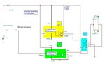
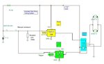
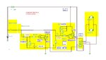
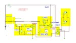
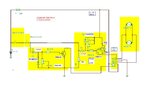
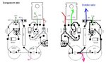
Forgive my ignorance. But could u explain how this circuit works? I'm not knowledgeable enough to tell by looking. Relays, I can usually tell or figure out. Circuits, I'm screwed... I'm thinking pulses play a part but I'm not sure. Also, keep in mind I'm trying to keep the circuit relatively small due to space constraints. This is my complete circuit thus far: IMAG0131.jpg IMAG0133.jpg

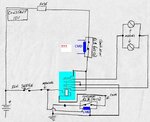
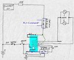
I figure 2 more relays shouldn't take up much more space. And I can tape them together like one unit. Is there a benefit to building "printed" or "logic" circuits, opposed to using just relays?
 

Attachments

  • Auto folding Vers 3.JPG
    Auto folding Vers 3.JPG
    74.4 KB · Views: 51
  • Auto folding Vers 4.JPG
    Auto folding Vers 4.JPG
    73 KB · Views: 49
Ok. I believe I understand the above circuits. The yellow relay is for extend, and the green relay is for retract. When either of the relays are pulsed, the circuit closes for the allotted time period, then resets. Thus, removing power from the circuit. The only thing I can't figure out, is how would you get the positive and negative pulses? From what I read, it seems like a positive pulse comes from the switch being across the hot lead. And the negative pulse comes from the switch being across the ground. I believe that's what the wolstentech site explained. I bought a SPST rocker switch for this set up, which I don't believe it will work with the above circuits. Seems like I would have to get a polarity reversing switch. Please correct me if I misunderstand any of this. Also, what is wrong with my proposed circuit in #58? Seems like it would do the same thing as the above circuits, without having to buy a new switch... Even though a new switch is really no biggie.
 

About your schematics (proposed #58), I don’t see some how to control RL1. (See the two possible connection attached).

Anyway, in the last schematics I have proposed a diagram for WOLSTENTECH Time-Delay Relays, but I didn’t have opportunity to test if WOLSTENTECH Time-Delay Relay can be triggered by a negative signal using also some small resistor between trigger terminal and GND.
 

Attachments

  • My 2nd version.JPG
    My 2nd version.JPG
    49.2 KB · Views: 46
  • My1.JPG
    My1.JPG
    50.7 KB · Views: 51

Oh crap! My bad... My Mirror Schematic002.jpg

How bout now???
 

You know what??? I'm just gonna try and build your timer circuit. I haven't been to sleep since yesterday cause I been up all night trying to figure this stuff out. I'm heading to Radio Shack in a little while to see if they have everything you list on your schematic. If I screw it up, I'm buying 2 DEI 528T time delay relays, add them to my circuit, and just hope I don't melt the mirrors off my truck!!!
 

Ok. All the components I got are according to your schematic, except the transistors and diods (IN4005).. I got as close as I could but Radio Shack only carries a small amount of components. Here are the components I got:IMAG0143.jpg IMAG0145.jpg IMAG0142.jpg IMAG0140.jpg IMAG0141.jpg


Will the circuit work with these alterations? Can I build it?
 

Well, :grin: need to change power transistors, I have used darlington type (very low base current consumption in order to obtain high time delay)
-1 pc NPN type : BDW93, TIP120, TIP121, TIP122, TIP140, TIP142
-1 pc PNP type : BDW94, TIP125, TIP126, TIP127 BDX34C, TIP136

Or just in case if you don’t find any of them
Transistors & analog ICs - Component parts - RadioShack.com
try to combine the normal power transistors you have now with small power NPN/PNP transistor, so need to buy also:

1 pc NPN (small signal transistor) 2N3904/BC109/BC173/2N2222/MPS2222/
1 pc PNP transistor (small signal transistor) 2N3905/BC179/BC256

Plus 2 additional diodes (1N4005 series)


Also very important for time delay, need large values for capacitors, as in the diagram 1mF=1000uF/35V, need to buy 2 pcs 1000uF/35V (or better buy 2 pcs 2200uF/35V).
If you we need a large delay buy also 2 pcs 10k resistors.


There’s also a mistake in the initial diagram for the ‘100 ohms’ resistor (high power 2W), in practice we need to lower down the power consumption so will use 3 in series to obtain 300 ohm…
 

Wow! That's quite a few changes. I need to keep this circuit as small and simple as possible. Don't forget, I'm stupid. So, tomorrow I'll call an electronics store I know and see if I can find those IN4007 diodes and the BDW transistors. Or a cross reference. I don't need a long delay either. Between 3 and 7 seconds is great. The timing in your video is pretty much on point. I'll also swap out the caps for 2 2200uF/35V. Non-polarized? Or doesn't matter? As for the 100 ohm resistor, I would like to use just one if possible. So, can I just get a 300 ohm/2 or 5 watt? (Is it an either or type of thing?) Or does it HAVE to be 3 100 ohms in series? And can you please post an updated schematic with your alterations? I want to take it with me to the electronics store and say "This is what I need".

---------- Post added at 20:23 ---------- Previous post was at 20:15 ----------

And am I to understand that any one of these will suffice? -1 pc NPN type : BDW93, TIP120, TIP121, TIP122, TIP140, TIP142
-1 pc PNP type : BDW94, TIP125, TIP126, TIP127 BDX34C, TIP136
 
Last edited:

1. Keep the 1N4005 diodes.
2. Main problem is related to the capacitors, need 2 pcs 2200uF/35V (polarized)
3. We need a pair of darlington power transistors, one piece NPN and second one PNP, but only darlington types. I have checked on RadioShack site, and seems they are short on PNP power darlington transistors, they have only the NPN type, model TIP120, so we must improvise on creating a darlington transistor using some additional PNP small signal transistor (any type ) plus a 1N4005 diode.
4. We need only one 300 up to 470 ohms resistor (a simple way to connect 3 100 ohms resistors in series).
5. Here we have the two diagrams, one for darlington type transistors, the other using two additional small power transistors.
 

Attachments

  • Auto DPDT relay small power transistors.JPG
    Auto DPDT relay small power transistors.JPG
    155.1 KB · Views: 61
  • Auto DPDT relay Darlington.JPG
    Auto DPDT relay Darlington.JPG
    151.3 KB · Views: 50

Some examples how to arrange the components on a small PBC board.
Components shown on the pictures just for reference purposes only. :-D
 

Attachments

  • PCB 2.jpg
    PCB 2.jpg
    234.1 KB · Views: 44
  • PCB1.jpg
    PCB1.jpg
    253.1 KB · Views: 50
  • modifications.jpg
    modifications.jpg
    261.7 KB · Views: 49

Ok. I'm going to head out for the 100ohm Resister, 2 Capacitors, and 2 transistors today. If this store doesn't carry them either, I'll order what I need online. I've waited this long. A few more days wait won't kill me. If they have the 1n4007 diodes I'm going to get those too. I can take the 1n4005's back to Radio Shack for a refund if I don't use them. Thanx for all your help mister_rf! I'll let you know if I got everything once I get back.
 

1N4005 are OK, no need to change.
The 100 ohms must be changed to 330-470 ohms.
 

Ok. He didnt have the BDW transistors, so i got 1 - NTE2342 - PNP and 1 - NTE2341 - NPN. I got 2 - 2200uF/25v caps, and a 300 ohm/2w resistor. I also got a pair of 1N4007 diodes anyway just in case. I rather have them and not need them, than need them and not have them. Can we work with this?
 

Well, when we have start drawing the first schematics, there was no need for some high current darlington transistors, relays do all the hard work. Now, using a single DPDT relay, we need to put some pressure also on PNP side, so as I can’t estimate the maximum consumption of the folding mirrors motors, I have chosen transistors supporting at least few amps, but as the NTE series rated 1 Amp full scale, need to combine NTE2342 with the TIP42 (plus one 1N4007 diode).
 

Attachments

  • Auto DPDT relay NTE2341_NTE2342.JPG
    Auto DPDT relay NTE2341_NTE2342.JPG
    141.5 KB · Views: 50

I tested 1.64A between mirror and ground when mirror was in its designated position. If that helps...
 

Yes, that’s way too much for the NTE transistor.
 

Components placed on a PCB.
 

Attachments

  • components.JPG
    components.JPG
    74.1 KB · Views: 45

So, what transistors should I need now. I can postpone the build until I get the right stuff. I want to do it correctly.
 

Status
Not open for further replies.

Part and Inventory Search

Welcome to EDABoard.com

Sponsor

Back
Top