Continue to Site

Welcome to EDAboard.com

Welcome to our site! EDAboard.com is an international Electronics Discussion Forum focused on EDA software, circuits, schematics, books, theory, papers, asic, pld, 8051, DSP, Network, RF, Analog Design, PCB, Service Manuals... and a whole lot more! To participate you need to register. Registration is free. Click here to register now.

Timer relay question! Help needed please.

Status
Not open for further replies.

yazen

Junior Member level 1
Joined
Jul 11, 2011
Messages
18
Helped
0
Reputation
0
Reaction score
0
Trophy points
1,281
Activity points
1,525
Hi All,

Hope you guys are doing well.

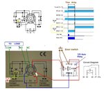
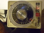
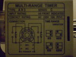
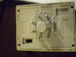
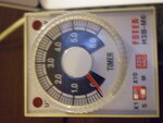
I have a question on how to energize a timer relay ( this is the timer **broken link removed**)

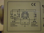
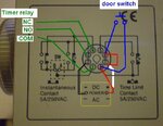
I know how to wire a timer relay, but this is the senario:

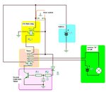
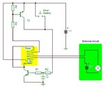
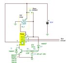
I need to have a push botton (normally closed) pressed to reset a circuit in my car, the way i wanna set it up is, to hook up the timer relay with the door switch, so when i open the door, the door switch would power up the timer, and the timer will reset the switch in few minutes. The only issue which i am having at the moment is that, i have connected the timer (-) to the door switch and (+) directly from the battery, so when i open the door it would energize the timer and when i shut the door the timer would loose power! and i am unable to achieve what iam looking for. Need an advice on how to connect the timer to the door switch and would get powered as soon as i open the door and would stay powered when i close the door so it would reset a switch after few minutes?

Thanks,
Yazen
 

Try this way.
You need a only a door switch (just a short pulse) to energize the timer relay. The relay must be programmed on ‘’C’ operation mode.
One pair of the contacts are in use to power-up the timer relay, the second one are for free use. End of the programmed time interval the relay will be disconnected automatically.
 

Attachments

  • Power ON delay.GIF
    Power ON delay.GIF
    48.2 KB · Views: 116
Last edited:

mister_rf, thank you for the reply.

The link to the time relay is wrong, sorry. Pictures of the relay which i have are attached here. So, if i connect 2&7 to energize the relay, and connect 8 to the door switch, it would be shorted with 6 but as soon as i shut the door the door switch will turn off and the relay will be useless here! what is the correct way of connecting it so that when i shut the door the relay pins 8 and 6 remain shorted?

Thanks,
Yazen
 

Attachments

  • P7120517.JPG
    P7120517.JPG
    1 MB · Views: 87
  • P7120516.JPG
    P7120516.JPG
    1 MB · Views: 94
  • P7120514.JPG
    P7120514.JPG
    1 MB · Views: 101

The whole idea to use a relay section in order to keep the power on after the door contacts open.
Second section of the relay are free to use it as you wish. See the diagram attached.
 

Attachments

  • New timer relay.JPG
    New timer relay.JPG
    44.3 KB · Views: 155
  • Like
Reactions: yazen

    yazen

    Points: 2
    Helpful Answer Positive Rating
mister_rt, Thanks a lot for your prompt response. Appreciated it.

I will just test it in the next 30-45 mins and report back.

Thanks again,
Yazen

---------- Post added at 22:43 ---------- Previous post was at 22:14 ----------

Apparently, the relay is out of order, will get another one tomorrow and report back.

Thanks,
Yazen
 

Hello mister_rt

I got a new time delay relay, and it worked. Thanks heaps.

I have few questions though :)

1) I need to set the timer to get triggered after three minutes, but the issue here is that, if i open the door for less than 10 seconds, nothing will happen to the relay! so i have to keep the door open for 10 seconds for the delay to get triggered! is there a way to reduce the time to 2 seconds or even 1 second?

2) i realized that when the relay is triggered it stays that way unless i disconnect the power supply manually. Is there a way to do that automatically. On the same circuit which i need to reset when i open the door, there is another switch which activates the circuit when turned on, can this switch when switched on turn off the time relay?

3) when the time relay is on all the time and over night, wouldnt it drain the car's battery?

4) is there a way to let the time relay trigger the rest switch and go off after its done its job?

I am sorry for asking so many question, please guys dont mind, i am just a beginner in the world of electronics.

Thanks again,
Yazen
 

I have now the timer datasheet.
This model was designed as ON DELAY TIMER so we need to use an additional 12V relay in order to be disconnected automatically after a preset time.

**broken link removed**


So we need to do some modification for the initial setup. :grin:
 
  • Like
Reactions: yazen

    yazen

    Points: 2
    Helpful Answer Positive Rating
Thanks you, mister_rt

Could you help me here for the modification and wiring of additional 12V relay please?

Thanks a million,
Yazen
 

Here you are...

Also need to set the timer on position B, in order to use the 1-3 contacts without any additional delay.
Time delay adjustable from the main timer knob.
 

Attachments

  • Relay timer v2.JPG
    Relay timer v2.JPG
    110.9 KB · Views: 110
  • Like
Reactions: yazen

    yazen

    Points: 2
    Helpful Answer Positive Rating
Hello mister_rt:

Thank you so much for all you help and support.

One thing i should have mentioned earlier thought, when i got a new time relay, its not the same as the previous one, picture of the new one is attached! kindly take a look at it and tell me if what you mentioned in your last replay would work on this relay.

Thanks again,
Yazen
 

Attachments

  • P7150522.JPG
    P7150522.JPG
    1.4 MB · Views: 109
  • P7150528.JPG
    P7150528.JPG
    958.5 KB · Views: 100

I think I need more info about how to control the external circuit.
Now, with using also an external relay, the timer can be trigger by a short contact of the door switch, (this contact = normally open) stay on power for the programmed period and automatically disconnect from the power supply end of the time.
The most important thing missing. What about the external contact?
There are some possibilities you may wish to implement:
1. NC normal closed contact ( closed for the power OFF), stay closed for a time period after we apply power to the timer, and then to be disconnected only for a short time (how long you need this ? ) after the programmed timer period has expired, later back to be closed
2. NC normal closed contact (closed for the power OFF), disconnected for the whole period timer ON, but reconnected when timer OFF
3. NO normal open contact, kept open for a time period after we apply power to the timer, and then to be connected only after the programmed timer period expired, (but for a short time – so how long you need this ? ), and later back to be open.
4. NO normal open contact (open for the power OFF), connected for the whole timer period ON, but reopened when timer OFF

Not all the options can be prepared with the actual timer, so need to choose what’s the timer action you expect.
 

Attachments

  • Option 1 to 4.GIF
    Option 1 to 4.GIF
    5.7 KB · Views: 103
  • Like
Reactions: yazen

    yazen

    Points: 2
    Helpful Answer Positive Rating
Thank you, mister_rt.

You have been a great help, thanks heaps.


Lemme give you more info about the external circuit which iam trying to reset, lets call it circuit "B"

Circuit "B" has two switches, one to turn it on and the other to turn it off. The first switch that turns it on is a reed switch! the other switch is a normal pushbutton switch (NC) once its pushed it opens the power supply and the circuit would tun off.

So i am trying to hook up a time delay relay instead of the second switch (pushbutton) to turn the circuit off.

When do i need to turn the circuit "B" off? i want to turn it off three minutes after i open the driver's door regardless if the car is on or off.

So this is what i am trying to achieve:

When i open the driver's door, the time relay should get energized regarles how long i keep the door open, and should stay energized even when i close the driver's door. After three minutes, the time relay should break the (NC) switch for 2 seconds which is enough for circuit "B" to turn off.

Your help is still needed please here. Do you think the time relay which i have already would work here?

Many thanks,
Yazen
 

In order to do the requested operation we need to add a second timer, just a power transistor, a capacitor and some resistors.
Can you manage this? :grin:
See details:
 

Attachments

  • Combined Timer.JPG
    Combined Timer.JPG
    38.6 KB · Views: 114
  • Like
Reactions: yazen

    yazen

    Points: 2
    Helpful Answer Positive Rating
On a second thought, I think we need to keep only solid state devices, so the version of the schematics: :grin:
 

Attachments

  • Timer version 1.1.JPG
    Timer version 1.1.JPG
    33.4 KB · Views: 109
  • Like
Reactions: yazen

    yazen

    Points: 2
    Helpful Answer Positive Rating
If i can manage on my own, i wouldnt have asked here :D lol thanks a lot.

Y

---------- Post added at 19:52 ---------- Previous post was at 19:44 ----------

On a second thought, I think we need to keep only solid state devices, so the version of the schematics: :grin:

Okay i will buy the items and try and build it tomorrow, one question though, could you please tell me what items do i need here?

and Could you number the time relay so i know which pin is where.

You are talking to a beginner here :D

Thank you so much for your time and help, really appreciated it sir.

Yazen
 

And what’s your opinion? Do you want to start this small project? :-D I can give you all additional details needed.

---------- Post added at 22:00 ---------- Previous post was at 21:57 ----------

OK, I'll prepare a list and update the schematics.
 

And what’s your opinion? Do you want to start this small project? :-D I can give you all additional details needed.

Yes sir, iam all set and willing to start this ASAP :D

---------- Post added at 22:00 ---------- Previous post was at 21:57 ----------

OK, I'll prepare a list and update the schematics.

Thats great, please do so. Thanks again :)


Yazen
 

Supplementary question.
What type of door contact are you using? A standalone (not connected to some additional devices) or the built-in door contact?
This is because I need to know if there’s a plus voltage on the contact side or a GND (chassis), in the previous schematics I use a temporary button connected to the positive side of the battery, changing to GND require some modification in the diagram.
 

mister_rt,

Its standalone switch, not connected to anything else. Its a NO switch, when the door is opened the switch connects to the GND and the light goes on inside the car.

Thank you and best regards,
Yazen
 

OK, in this case we can use it. See details in the schematics, for the second relay you can use any type, later to decide the pinouts, will see what you buy from the store. :grin:

final shopping list:
1 pcs 12V relay
1 pcs resistor 470 ohms- 680 ohms/ 0.25W-0.5W
1 pcs resistor 2.2k - 2.7k/0.25W-0.5W
2 diodes 1N4001 - 1N4007
1 capacitor 470uF / 25 -35V (values not critical 330uF -680uF /16V - 35V)
For the power transistor we need a NPN darlington type, ex: BD679, BD681, TIP121, etc.
 

Attachments

  • Combined Timer v1.JPG
    Combined Timer v1.JPG
    101.4 KB · Views: 110
Last edited:
  • Like
Reactions: yazen

    yazen

    Points: 2
    Helpful Answer Positive Rating
Status
Not open for further replies.

Part and Inventory Search

Welcome to EDABoard.com

Sponsor

Back
Top