Continue to Site

Welcome to EDAboard.com

Welcome to our site! EDAboard.com is an international Electronics Discussion Forum focused on EDA software, circuits, schematics, books, theory, papers, asic, pld, 8051, DSP, Network, RF, Analog Design, PCB, Service Manuals... and a whole lot more! To participate you need to register. Registration is free. Click here to register now.

Timer relay question! Help needed please.

Status
Not open for further replies.
Alright, I will hit the roads first thing tomorrow morning and buy the stuff. Will report back as soon as i buy the stuff.

Thanks, Yazen
 
Last edited:

I just noticed one thing, in your last circuit, the door switch is connected to the positive side of the circuit, but in the car its connected the negative. Am i missing something or it is supposed to be this way?

See attached picture (this is how the switch is connected in my car)

Thanks,
Yazen
 

Attachments

  • Screen shot 2011-07-16 at 3.59.57 AM.png
    Screen shot 2011-07-16 at 3.59.57 AM.png
    38 KB · Views: 76

:grin:
Supplementary question.
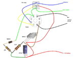
What type of door contact are you using? A standalone (not connected to some additional devices) or the built-in door contact?
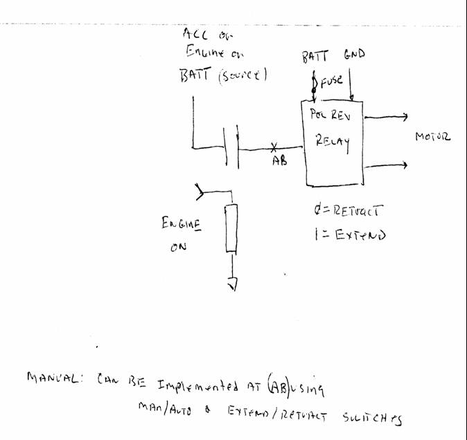
This is because I need to know if there’s a plus voltage on the contact side or a GND (chassis), in the previous schematics I use a temporary button connected to the positive side of the battery, changing to GND require some modification in the diagram.

That’s way we need to do some changes in the shopping list, instead of the NPN transistor buy a PNP darlington transistor, ex BD646, BD648, BD678, BD680, BD682, TIP 116,TIP125/ TIP126, TIP127, TIP136, BDX34C.

Also. Just in case we need to change timings , buy some additional resistors:
1 pcs 1K/0.25W
1 pcs 2.2k/0.25W
1 pcs 3.3k-3.9K /0.25W
 
Last edited:
  • Like
Reactions: yazen

    yazen

    Points: 2
    Helpful Answer Positive Rating
Hello mister_rt,

I got these items:

1 pcs resistor 470 ohms /0.25W
1 pcs resistor 2.2k/0.25W
2 diodes 1N4001
1 capacitor 470uF / 35V
1 NPN transistor TIP127
1 pcs 1K/0.25W
1 pcs 2.2k/0.25W
1 pcs 3.3k/0.25W
12VDC relay

Whats next?

Many thanks,
Yazen
 

The new schematics, almost the same :grin:, except the power supply and diodes on reverse, need to have details for the pinout of the 12V relay.
 

Attachments

  • Combined Timer v1 pnp.JPG
    Combined Timer v1 pnp.JPG
    110 KB · Views: 75

This type of transistor TIP127 has also an internal diode, so we may decide not to mount the second diode ‘D’, or not, anyway that’s not so important now. What about the 12v relay? Did you say something about a ‘Toshiba relay’, is this available now?
 

Great, thanks a lot sir, I am gonna construct this in the next 45 mins and will report back

Thank you, mister_rt


Yazen
 

So what to do now regarding the diodes?

I already have 12vdc heavy duty car relay, see attached picture please.

Thanks,
Yazen
 

Attachments

  • P7130519.JPG
    P7130519.JPG
    1 MB · Views: 66
Last edited:

Please advice, should i construct the circuit with the diodes or not?

Thanks,
Yazen
 

See the diagram. On diode missing, not important, the transistor has one built-in for.
 

Attachments

  • timer PNP.jpg
    timer PNP.jpg
    230.4 KB · Views: 65
Last edited:
  • Like
Reactions: yazen

    yazen

    Points: 2
    Helpful Answer Positive Rating
Thank you, mister_rt

I will construct the external circuit and this one today and will report back.

Thanks once again,
Yazen
 

YES YES YES :D it worked like a charm. Cannt thank you enough mister_rt, you've been a great help, may *** bless you.

This might sound crazy but its true, I've been testing this device from the last 3 hours :D and it worked every time :)

Thank you so much mister_rt really appreciated it :)


Yazen
 

Re: Relay circuit design question!

Hey. I'm new here and wanted to see if u guys can help me. I just bought 2 power folding side mirrors for my truck (2004 Trailblazer). The truck is not equipped for them so I have to build my own controller. Polarity determines whether the mirrors extend or retract (mirror motors have only 2 leads). I could easily do it with a manual switch, but of course it has to be cooler than just that. I'm trying figure out the simplest circuit I can design using the factory power mirror directional control switch. When its in the neutral position I want to be able to nudge it (in whichever direction, doesn't matter) and have the mirrors extend and retract. A momentary switch type of thing. But, I also want them to extend when I turn the vehicle on, then retract when I turn the vehicle off. Anyone here have any ideas how I might accomplish this with the least amount of headache? Or setting my car on fire!!! Don't know whether to use timed relay, DPDT polarity reversing relay, latching relay, dual coil relay. I'm pretty stuck right now. I'm a novice with circuit design so please be patient with me. Learning as I go along. Also wondering if solid state circuit is an option...
 

In order to improvise the control system we need to have additional details about mirrors. Does the mirrors have implemented some sort of protection, not to force motors for a sustained power up connection? What’s the pinout/diagram for the switches/buttons on the control panel?
 

Simple relays circuit so the mirrors open when the car comes on and closes them when the car is off...
 

Attachments

  • Folding mirrors.JPG
    Folding mirrors.JPG
    100.9 KB · Views: 65

excerpt from ALLDATAdiy.com


Fold motor in each of the outside mirrors, if equipped with power fold mirrors-Provides extend and retract movements of the mirror and is serviced as a complete mirror assembly Each of the outside power mirrors contains 2 reversible motors to provide horizontal and vertical movement of the mirror glass. The vertical motor operates the up and down directions and the horizontal motor operates the left and right directions. If equipped with power folding mirrors, each outside power mirror will contain a reversible fold motor to operate the extend and retract functions. Each of the mirror motors are circuit breaker protected.

Power Mirror System Controls
The power mirror switch incorporates a 3-position mirror select switch and a 4-position mirror direction switch. The mirror select switch allows the operator to select the mirror to be moved by rotating counterclockwise to the L position for the left power mirror, rotating clockwise to the R position for the right power mirror, or the center which is the neutral/fold position. The mirror direction switch is a 4-position switch that allows the operator to move the selected mirror up, down, left, or right. The mirror direction switch also functions as the folding mirror switch. When the selector switch is in the neutral/fold position, activate the mirror direction switch to the left to extend the mirrors and right to retract the mirrors.

FOLDING MIRROR SYSTEM

Folding Mirror System Controls

When the mirror select switch is in the neutral/fold position, it allows the operator to retract or extend the outside rearview mirrors from a single switch. The mirror fold switch incorporates solid state circuitry to allow this single switch input to alternately perform both extend and retract functions.

Folding Mirror System Operation

The mirror fold switch receives power through the battery supply voltage circuit and the EXT LPS fuse and a constant ground. The mirror extend and retract control circuits are connected to ground through the normally closed contacts of the mirror fold switch. When the mirror fold switch is activated, the solid state circuitry will energize either the extend or retract relay, depending on the last function, which supplies battery voltage to the fold motor through one of the control circuits. The other control circuit is connected to ground through the normally closed contacts in the mirror fold switch and the mirror extends or retracts.

 
Last edited:

That circuit looks great mister_rf. Do i really need the timers though? I want the circuit as simple as possible. Not only for cost and simplicity, but so that it can hopefully fit inside the door with the other switches. A friend of mine sent me the following diagram and explanation. Do you think that it will work for my needs?

Basically, a DPDT relay is configured so that when it's normally closed power is applied to the motor so that it extends. e.g. when the coil is not powered, the motor will retract. The motor is supplied with fused battery power.

Another relay basically detects whether the engine is on. It could come the ECM fuse. When the engine is on, the DPDT relay switches state and the motor extends.

No power would be drawn when the motor is set to retract.

Manual control of the mirrors could be implemented with an auto/on switch and an extend/retract switch. The latter only works in manual mode. These switches would be inserted at the AB position in the diagram.


---------- Post added at 20:51 ---------- Previous post was at 20:49 ----------

I'm not sure, but your diagram seems to reflect that the mirrors have separate relays for both the left and right mirrors. I only need to control the driver side mirror. The passenger mirror control motor will piggyback off the driver side. I also don't understand the significance of the directional switches in the diagram. Remember, I'm an idiot (just a step above moron) when it comes to circuit design. So please keep it as simple as possible for me. Sorry if its a bit frustrating...
 

In this case, just for a single command we can simplify the diagram. Really, I don’t know if the mirror have implemented some motor protection, need to test it anyway, that’s the main reason I have set some custom made timers…
 

Attachments

  • Single mirror cmd.JPG
    Single mirror cmd.JPG
    97.2 KB · Views: 66
  • Single mirror cmd 2.JPG
    Single mirror cmd 2.JPG
    95 KB · Views: 64
Last edited:

I'm fairly sure that when the mirror reaches its desired position it terminates power. So, to simply things, lets presume that that is the case. If not, I have a 1 year warranty period to be proven wrong...
 

Status
Not open for further replies.

Part and Inventory Search

Welcome to EDABoard.com

Sponsor

Back
Top