Welcome to our site! EDAboard.com is an international Electronics Discussion Forum focused on EDA software, circuits, schematics, books, theory, papers, asic, pld, 8051, DSP, Network, RF, Analog Design, PCB, Service Manuals... and a whole lot more! To participate you need to register. Registration is free. Click here to register now.
I am not sure what exactly you are looking for but I will go over it briefly.
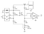
So the resistor across the input sets the gain of the amplifier (there is a formula for it in the datasheet). You have your reference voltage divider with tunable resistor (Potentiometer) and biased thermocouple that is feeding into the inputs. The amplifier appears to be inverting (the positive is to ground). The circuit diode in the thermocouple interface is for the cold junction compensation (the temperature reference for the circuit for offsets). So besides that what do you need to know more or have questions on?
This site uses cookies to help personalise content, tailor your experience and to keep you logged in if you register.
By continuing to use this site, you are consenting to our use of cookies.