Continue to Site

Welcome to EDAboard.com

Welcome to our site! EDAboard.com is an international Electronics Discussion Forum focused on EDA software, circuits, schematics, books, theory, papers, asic, pld, 8051, DSP, Network, RF, Analog Design, PCB, Service Manuals... and a whole lot more! To participate you need to register. Registration is free. Click here to register now.

thermistor cold is high impedance and hot is low impedance?

Status
Not open for further replies.

PrescottDan

Banned
Full Member level 1
Joined
May 1, 2014
Messages
119
Helped
0
Reputation
0
Reaction score
0
Trophy points
16
Visit site
Activity points
0
A thermistor when cold is high impedance and hot is low impedance?

A Thermistor is always on the primary of the AC line transistor?

A Thermistor is only used in switching power supplies?

A Thermistor controls the in rush current? so the filter capacitors don't get damaged
 

There are two types of thermistors
PTC: Impedance increases with temperature
NTC: Decreases
Since NTC thermistors have a higher impedance initially at startup, they do limit current inrush
 

Since NTC thermistors have a higher impedance initially at startup, they do limit current inrush

Why are thermistors at a high impedance when there is current first applied to them and slowly a delay time for the thermistor to be a low impedance?

A Thermistor has a delay time or decay time from high impedance to low impedance

A Thermistor has a Threshold voltage or current, to turn it On?

How does a thermistor limit the in rush current?
 

A thermistor is essentially a resistor whose resistance depends strongly upon its body temperature. 100 degrees rise may reduce the initial resistance by as much as as 100 times, as opposed to normal resistors where he resistance would generally increase by roughly .01% to .02% for a 100 degrees change.
It is apparent then that the initial current through an NTC thermistor will be far less than what it it would be a few seconds later after heating up. This explains the inrush current limiting property of an NTC thermistor
 

Are Thermistors only used for switching power supplies? and why only for switching power supplies?

Is a thermistor only used on the primary or secondary of a AC line transformer?
 

Having known the property of a thermistor, you can use it anywhere you please to

So you can just place it in series or in parallel anywhere in the power supply?
 

Place it anywhere in the power supply?? My mind is racing.
Make a video of you connecting a powerful NTC thermistor parallel to the output of the power transformer of a power supply.

About 50 years ago a coin-shaped NTC thermistor was sold to be placed in a light bulb socket. Then the incandescent light bulb lasted much longer than in an ordinary socket.
What is the resistance of the filament of a cool light bulb? It is a PTC resistor so its resistance is much lower than when it is 2000 degrees C so it creates a huge inrush current that causes a slightly used light bulb to instantly burn out when it is turned on.
The NTC thermistor is in series with the light bulb and has a high resistance when it is cool so the light bulb does not get a high inrush current when it is turned on, then the thermistor warms up and decreases its resistance so the light bulb ramps up its brightness until it is normally bright.

Then doesn't it make sense to connect an NTC thermistor in series with the input of a power supply to prevent a high inrush current when the main filter capacitors charge?
 

Then doesn't it make sense to connect an NTC thermistor in series with the input of a power supply to prevent a high inrush current when the main filter capacitors charge?

Yes true, but where to put it in series

On the primary, secondary?

Mostly i have seen thermistors screwed down on a heatsink of power transistors

The Thermistors are in series with the power amps, power transistors to detect something

The Thermistors are connected to a current sensing circuit in the power amp?
 

I didn't literally mean anywhere!
I meant... having learnt the characteristics of a thermistor connect it to any design/circuit that it suits. Why be limited only to SMPS circuits?
And ofcourse, a person who knows its characteristics, will not place it in parallel with a transformer!
 

Mostly i have seen thermistors screwed down on a heatsink of power transistors
The Thermistors are in series with the power amps, power transistors to detect something
The Thermistors are connected to a current sensing circuit in the power amp?
Obviously, the thermistor does not limit a current surge, it is used as a temperature sensor. Frequently a diode or a transistor junction is used as a temperature sensor to keep a power transistor from having thermal runaway because it changes exactly the same as the power transistor that is trying to increase its current when it gets hot which causes it to increase its current more which causes it to get hotter which causes more current which causes more heat which causes more current which causes more heat ......
See how thermal runaway is caused then look at a schematic to see how a diode is connected to the power transistor to prevent it?
 

See how thermal runaway is caused then look at a schematic to see how a diode is connected to the power transistor to prevent it?

Yes I have seen a diode across the emitter to collector of power transistors

The Diode is sometimes reversed or forward polarity , I have seen it both ways

Not sure what the polarity of the diode does when it's connect like this for thermal runaway
 

I have never seen a diode across the emitter to collector of a power transistor, usually a diode is across the load to arrest a voltage spike when an inductive load is turned off.

In an audio power amplifier a diode is a thermistor across the emitter to base. When the amplifier heats up then if the base-emitter voltage of a power output transistor stays the same then the collector-emitter current increases that causes more heating that causes more current that causes thermal runaway.
If the base-emitter voltage is reduced a little when it heats then the current runaway is stopped.

A diode reduces the voltage across it when it heats exactly the same way that a runaway transistor needs it reduced across its base-emitter for preventing the thermal runaway. Usually the diode is bolted to the heatsink of the power transistor or a junction of a transistor can be used as a thermistor diode since it has a metal tab that can be bolted.

Here is the schematic from the datasheet of an LM386 little audio power amplifier showing two diodes that thermally compensate the current in the output transistors. Millions of different audio amplifiers use this kind of thermal compensation.
 

Attachments

  • LM386 schematic.png
    LM386 schematic.png
    26.3 KB · Views: 147

  • All materials have a thermal coefficient. Ones with high sensitivity and accuracy are called thermistors.
  • All Diodes have a linear negative voltage characteristic with some variations in materials.
  • Metal Oxide disks may be (+)PTC or (-)NTC
  • They are called "resettable fuses" and "inrush current limiters" or ICL's , respectively.
  • ICL's have approx. 10:1 ratio for resistance regulating its own resistance when they get hot from 25C to ~85C
  • Tungsten filaments have an R range of 1:10 from 25C to 2000C thus have 10:1 surge current.
  • PTC Polyfuse™ have a dynamic range of several decades which triggers at the self regulating temperature of 85C approx.
  • Below you can see ICL's are conveniently rated or Imax and uF capacitance on AC rectified line.

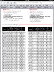
image.jpg
FYI only .. Tony Stewart EE'75
 

Some thermistors I have seen are across power diodes or power transistors

Other Thermistors I have seen are in the power supply and trigger a crowbar SCR , you have to unplugged the power to "reset" the crowbar SCR circuit

I have never seen a diode across the emitter to collector of a power transistor

Well take a look, what does this diode do across the emitter to collector?
Power Transistor with diode.jpg
 

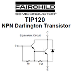
You do not show a power transistor, instead you show a Darlington Transistor that has two transistors, two resistors and a diode.
The diode is usually not used and is not mentioned in the datasheet so its ratings are not known.
It is probably just part of the manufacturing process.
This is from a datasheet of a Darlington Transistor:
 

Attachments

  • darlington transistor.png
    darlington transistor.png
    13 KB · Views: 163

But what would you think that diode does? and why would they use a diode like this only for a Darlington Transistor?

It balances or stabilizes the darlington transistors output?
 

As audioguru said it serves no,purpose (other than to protect itself) and is likely an inherent part of the epitaxial process of a darlington.

Wheras Avalanche protected MOSFETs will use zeners to,protect themselves.
 

But what would you think that diode does? and why would they use a diode like this only for a Darlington Transistor?

It balances or stabilizes the darlington transistors output?
The diode is reverse-biased so it never conducts and does nothing.
Since it does nothing then how can it balance or stabilize anything??
 

Status
Not open for further replies.

Part and Inventory Search

Welcome to EDABoard.com

Sponsor

Back
Top