Continue to Site

Welcome to EDAboard.com

Welcome to our site! EDAboard.com is an international Electronics Discussion Forum focused on EDA software, circuits, schematics, books, theory, papers, asic, pld, 8051, DSP, Network, RF, Analog Design, PCB, Service Manuals... and a whole lot more! To participate you need to register. Registration is free. Click here to register now.

1920s vintage speaker with a guitar amp (Impedance problem)

bzblues

Full Member level 1
Joined
Oct 11, 2020
Messages
99
Helped
0
Reputation
0
Reaction score
2
Trophy points
8
Activity points
822
Hello everyone!

(I apoligize in advance if I ask noobie quiestions, but I'm a beginer in this matter)

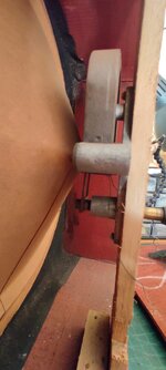
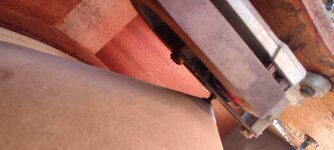
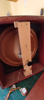
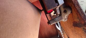
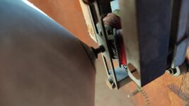
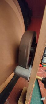
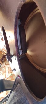
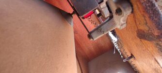
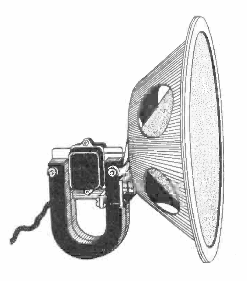
I have a 1920s vintage speaker that is in a pristine condition! I intent to use this speaker with a small powered guitar amp that I've built. The guitar amp is called "ruby" wich is a 9v powered 1watt amp and it works well with 4ohm and 8 ohm speakers.

This vintage speaker is 1000 ohms and obviously doesn't work out porpperly with the guitar amp because of the impedance. So, I started to do some research and I found out that you would have to use a "step down" or "step up" impedance transformer. Now, here is when I hit the wall because its an unknown territory for me (yet)

I found out a website that allows you to calculate the type of transformer that you would have to use, but it seems that the results are not "realistic" but still, maybe I'm missing a few things.

What would you recomend to do in this particular scenario? again, its a small guitar amp (1 watt, 9V powered, works well with a 4ohm speaker) and I want to use it with this 1920's vintage speaker that is a 1000 ohm.

Is it possible to do?

Thanks a lot in advance!

Brian.
 
Hi,

impedances transform with squares of winding turns.

this means: if the speaker is 1k and the amplifier is designed for 8Ohms, then
ratio = sqrt(1000/8) = about 1:11.

So you may use a 3V:33V transformer.
I guess it´s difficult to find one.
So you may try a 230V:20V transformer. It my output something, but maybe not that good at higer frequencies.
or 230V/18V or 230V /16V.

For sure best is to get/design a true audio transformer.

Klaus
 
Another option could be to insert a basic audio amp between guitar amp (call it a preamp as it has such weak drive) and your choice of speaker. Let the little amp do the small-signal job, and give it a buddy for the heavy lifting.

Because with that weak drive, a xfmr may match impedance but it cannot add power to signal so you may just get "clean but inaudible".
 
Speakers I encountered from that era came from a public address (PA) system. In the cabinet was the speaker and attached transformer. I learned it was common to have 70 volts driving old PA systems. This allowed two conveniences:
a) speakers could be strung together with tiny wires for lengthy runs.
b) a speaker could be added yet without taxing noticeable power from the existing setup.

All this was possible by putting a step-down transformer in every speaker. 70V small current through the wiring, then it became a few volts at greater Amperes through the speaker. The 70V side had high impedance. Did you open up the cabinet and see such a transformer? It may be feasible to disconnect it. I'll bet the speaker is low impedance if it's like modern speakers.

Or else to install a transformer, try a 'doorbell' type used to step down house voltage to about 20 VAC. A hardware store should carry them. Since it works on 50 or 60 Hz, it should be compatible with guitar's low E (82 Hz).

www.homedepot.com/c/ah/how-to-find-and-test-a-doorbell-transformer/9ba683603be9fa5395fab90dd1f0bcf
 
To get 1W into a 1k speaker needs V squared over R to be 1 watt .
Or V = square root of 1000 ohms per Watt = 31 V
Yet the Ruby was based on an LM386 which only puts out 0.5 W at reasonable distortion, but you can use 12V if it can handle twice the heat with 8 AA batteries or 3 Lithium Polymer 18650 cells 3.6V nom. Each. That might need a bigger heating if you can make it.

so you only get 6Vpp clean out of 9V or 8V clipped. Thus a step-up transformer is needed to boost the voltage 31V/6V = 5 which makes the 1k speaker look like 1k/(5*5) = 40 Ohms.

But the real problem is old speakers did not have magnets and thus used electromagnets with electricity you don’t have in the Ruby. You may confirm this if it has 4 wires.

But if you can find an old Philips 12” 8 Ohm speaker and put it in a really big K3 particle board box with a reflex hole then 1Watt is amazing . Or mount it inside your wall between the 14.5” gap between studs lol. You might find a few walls vibrating.

I was using peak-peak power incorrectly like marketing did once and not average which LM386 correctly uses.

But we won’t talk about that or even mention RMS power which is another error.
 
But the real problem is old speakers did not have magnets and thus used electromagnets with electricity you don’t have in the Ruby. You may confirm this if it has 4 wires.
Good point. If I remember right, the voice coil of these old speakers didn't expose high impedance (e.g. 1k). The prerequisite of this thread may be erroneous.
 
Hello, everyone! thanks for the replys

Here are some pictures. I have 3 speakers of this kind and they all have the same type of coil and magnet. The screw in the back acts as a On/off switch I would say. You screw it and it makes contact and you can hear the speaker work.

Sorry for the messy pics, its not easy to shove the cellphone. The back lits are not possible to open except for one.

Here is more info about one of the speakers: http://earlywireless.com/celestion_c12_picinfo.htm

Cheers!
 

Attachments

  • 6b100eab-c2fa-483c-82e5-386a3073ff2c.jpg
    6b100eab-c2fa-483c-82e5-386a3073ff2c.jpg
    125.6 KB · Views: 46
  • 8bebd4e8-63a7-43e4-927d-94f3270d55f3.jpg
    8bebd4e8-63a7-43e4-927d-94f3270d55f3.jpg
    134.1 KB · Views: 66
  • 39a6045a-d52b-4382-945b-632ef3f68d4a.jpg
    39a6045a-d52b-4382-945b-632ef3f68d4a.jpg
    117.6 KB · Views: 46
  • 61d548e8-b284-419b-8b5c-0e8dbba30e8f.jpg
    61d548e8-b284-419b-8b5c-0e8dbba30e8f.jpg
    132.6 KB · Views: 49
  • 80f0610d-2f85-40e1-bb52-ee5a220780df.jpg
    80f0610d-2f85-40e1-bb52-ee5a220780df.jpg
    114.9 KB · Views: 52
  • 88f38c44-20fa-4a5d-8151-0bc3a4880a18.jpg
    88f38c44-20fa-4a5d-8151-0bc3a4880a18.jpg
    89.6 KB · Views: 51
  • c90341f8-5892-4253-ae06-73e38457010c.jpg
    c90341f8-5892-4253-ae06-73e38457010c.jpg
    147.5 KB · Views: 48
  • d26f283a-955c-4789-bbf3-0b46b082049b.jpg
    d26f283a-955c-4789-bbf3-0b46b082049b.jpg
    126.3 KB · Views: 50
The screw in back as I understand is a sensitivity adjustment that opens/closes the magnetic gap. If you start watching video around 5 minute mark you will see a similar screw adjustment.

 
Post #7 pictures clarifies that it's a "moving iron" (electromagnetic) loudspeaker which actually exposes high impedance. You should try a transformer with about 10:1 to 15:1 winding ratio, as suggested. Simple transformers with two windings attenuate high frequency components due to their leakage inductance. Audio transformers should use interleaved windings, but for first test, a mains transformer will work.
 
I have to ask: why do you want to use a 100-year-old speaker that is totally ill-suited for its intended purpose with a cheezy low-fidelity 1W amplifier?
I really have to question your evaluation of it as being "pristine". I'd bet that the cone and surround are dried out and crispy.
 
The LM386 amplifier IC produces 1W into 8 ohms when powered from 9VDC. But then it is clipping like crazy with very high distortion. Barely clipping, its output power is 0.56W and its distortion is fairly low.
When its speaker is 4 ohms then its heating almost doubles but its output power is almost half.
 
An effective tactic is to bridge the load (speaker) between two identical amplifiers. Feed the same signal to them except you must contrive something so that one amplifier receives inverted phase compared to the other (aka 180 degrees). The load receives bipolar AC at much greater amplitude.

The speaker (or transformer) is then no longer connected to ground. As a benefit you can omit the DC blocking capacitor at the output. (Often it's 200 or 400 or 1000 uF with the purpose of sending AC only to the speaker.)

In some cases you can tap into the first amplifier somewhere in order to get the inversion of the original signal. Or else build a phase splitter.
 
Good point. If I remember right, the voice coil of these old speakers didn't expose high impedance (e.g. 1k). The prerequisite of this thread may be erroneous.
>1k winding resistance for the voice is real in order to make tube high impedance practical.

This uses an early permanent magnet.

Reed mechanisms use a flat strip of spring steel anchored at one end, the other end moved by the magnetic field from the voice coil. The reed moves a cone or pleated paper diaphragm. It was meant to be driven directly from the Triode with high voltage DC with AC sound modulation, so the DC bias polarity matters.

"A lot of moving iron speakers have no damping. This means the moving member resonates freely in the audio band. This is bad news for sound quality, but introducing damping heavily reduces sensitivity. This was impractical in pre-war times when amplification was very expensive, so moving iron has a history of being used with no damping."

You would have to rewind the coil to work on low voltage DC or forget it.

1705175472449.png


Last edited:

LaTeX Commands Quick-Menu:

Part and Inventory Search

Welcome to EDABoard.com

Sponsor

Back
Top