Continue to Site
Follow along with the video below to see how to install our site as a web app on your home screen.
Note: This feature may not be available in some browsers.
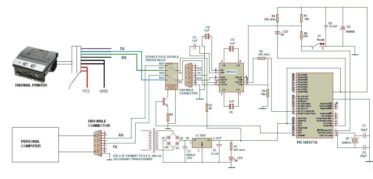

???this printer has a charger connected to it
If so, it can't be identified in your schematicso i dont hav to bother about the power supply for it
We can't know. Check the documentation shipped with the printer. Or ask the supplier.can u pls tel me if i hav to connect pin no 1 and 2 to ground and pin no 3 and 4 to vcc of power supply of my circuit
