Continue to Site

Welcome to EDAboard.com

Welcome to our site! EDAboard.com is an international Electronics Discussion Forum focused on EDA software, circuits, schematics, books, theory, papers, asic, pld, 8051, DSP, Network, RF, Analog Design, PCB, Service Manuals... and a whole lot more! To participate you need to register. Registration is free. Click here to register now.

test pic microcontroller

Status
Not open for further replies.

sri lakshmi

Newbie level 6
Joined
Jan 20, 2009
Messages
11
Helped
0
Reputation
0
Reaction score
0
Trophy points
1,281
Activity points
1,346
how to test a microcontroller

I have written a simple led program which makes portb highand leds glow.i am able to program it.but there is no output at portb. what does this mean is the pic working or not.
 

Which PIC are you using?
Have you connected the LED in the right direction?
Have you connected the LED to the right PIN ?
What oscillator is used? External or internal?
If external is programmed and no crystal is used, the program will not execute. Check for these points. Good luck
 

If you are still stuck, post your program code and a circuit diagram so we can see where the problem is.
 

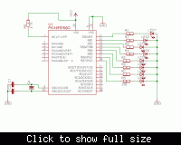
i have attached the shematic and program

i am using pic16f876 microcontroller

schematic


program
#include "16f876..h"
#USE DELAY( CLOCK=20000000 ) /* Using a 20 Mhz clock */

#FUSES XT,NOWDT,NOPROTECT,NOPUT
/* Use XT mode, No Watch Dog, No Code Protect, No Power-up Timer */

#byte port_b=6 /* define the location of register port_b */


void main(){

set_tris_b(0); /* set port_b to be outputs */
port_b = 0; /* initialize All port_b outp/uts to be zero */
// value = 0x10;

while( TRUE )
{
port_b = 0x01;
DELAY_uS(10);
port_b = 0x02;
DELAY_uS(10);
port_b = 0x04;
DELAY_uS(10);
port_b = 0x08;
DELAY_uS(10);
port_b = 0x10;
DELAY_uS(10);
port_b = 0x20;
DELAY_uS(10);
port_b = 0x40;
DELAY_uS(10);
port_b = 0x80;
DELAY_uS(10);

}
}
 

For one, you should use HS instead XT as the oscillator crystal settings since you are using a 20MHz clock according to your code.

Second, a 10us delay is ridiculously short, meaning each LED barely gets enough time to activate before being turned off again. Set the delay to at least above 100ms in order for the human eye to physically observe it.
 

actually that 10us i have tested for simulation.while programming on chip i used 1000ms.
 

NB !!!

If you are using high frequency you need very stable voltage. Minimum is 5V ... 5,5 max.

I suggest you to download a program (HEX) from internet.
 

take the correction by DSNet. if same problem, test with another chip.
 

Status
Not open for further replies.

Similar threads

Part and Inventory Search

Welcome to EDABoard.com

Sponsor

Back
Top