Continue to Site

Welcome to EDAboard.com

Welcome to our site! EDAboard.com is an international Electronics Discussion Forum focused on EDA software, circuits, schematics, books, theory, papers, asic, pld, 8051, DSP, Network, RF, Analog Design, PCB, Service Manuals... and a whole lot more! To participate you need to register. Registration is free. Click here to register now.

switching between two outputs

Status
Not open for further replies.

mingasss

Newbie level 3
Newbie level 3
Joined
Mar 22, 2015
Messages
3
Helped
0
Reputation
0
Reaction score
0
Trophy points
1
Visit site
Activity points
29
Hi guys, I would really appreciate if someone could give me advice on how to build circuit for this case. On my circuit input I have slowly arising voltage from 0V to 10V, and on my circuit I have 2 outputs. When input has 0V-5V, first output has to be active, but when voltage rises from 5V-10V, first output has to deactivate and second output become active. And vice versa, when voltage decreasing to less than 5V, second output has to deactivate and first become active.
5V is the point where output changes, depending on voltage.
I was thinking to use 5V or 6V relay which gets active when voltage gets close to 5V. But relay coil will always use energy, which is not good in my case, as I need as much as possible voltage and current on outputs. Can you help to project switching between two outputs using transistors or comparators circuit? Thanks in advance.

For your task using comparators is best. Find the Specifications for e.g. LM311 you can find a detailed instruction how to use it. There are many other new models, too.
 

For your task using comparators is best. Find the Specifications for e.g. LM311 you can find a detailed instruction how to use it.

a comparator will indicate when the input voltage is above or below a certain voltage. You might look at something like the CD4066 [or discrete mosfets] for the actual switching.

The output of the comparator would be direct input to one 'switch'. A logic inverter also feed by the comparator would be input to the other 'switch'.

When Vin > 5V the comparator goes high, 'switch' 1 turns on, allowing output-1, 'switch'2 is off, so no output-2.

When Vin < 5V the comparator goes low, 'switch' 2 turns on, allowing output-2, 'switch'1 is off, so no output-1.

- - - Updated - - -

You could also use a [resistor and] zener diode, or LEDs to provide the trigger. But both need some current [several mA] from the input to work properly.
 
Last edited:

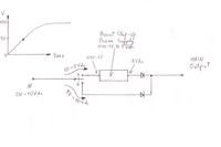
Thanks for your quick reply. To make it more clear I have drawn a plan of my circuit and hosted this picture here: **broken link removed**
In my circuit I use power step up booster, because on main output I need reach 5V as quick as possible, but when voltage reached more than 5V on main input, I need to switch from step up booster direct to main output, otherwise I will damage my power step up booster. I am not very strong in electronics, its still not clear for me how to use comparator, as my voltage rising from 0V to 10V on main input. so how can I compare my voltage on comparator if, for example, on main input will be 0,5V? I would really appreciate if you would draw a quick plan to explain. Thank you very much in advance.

 
Last edited by a moderator:

not to dissuade you but it would be simpler to just limit the voltage to the booster - though it would be inefficient

you don't say the current levels...............how much current does the booster supply [or much current can the source supply]?

once the voltage exceeds [5V] will it go down?

As you don't have much electronic experience, I strongly urge you to take a simple approach FIRST, and then try a more advanced approach.
 
Last edited:

Hi, thanks for you reply. I don't want to limit voltage on the booster, I want to switch it off when main input reaches over 5V. My main input has low current, around 200mA-700mA. So when main input goes over 5V, I want to direct all voltage to main output, so I won't loose any energy on booster at this time. Thanks
 

.... its still not clear for me how to use comparator, as my voltage rising from 0V to 10V on main input. so how can I compare my voltage on comparator if, for example, on main input will be 0,5V?

quick and basic tutorial on comparators [ignore the 741 op-amp stuff] http://cornerstonerobotics.org/curriculum/lessons_year1/ER Week15, Comparators.pdf
your comparator would be powered, of course, by the boosters output
you would want to select a low-power single power supply comparator

you can not directly switch based on 5V as it too close to the supply voltage

Vref or the non-inverting input [+] would be taken from a voltage divider [2 equal valued resistors in series] from 'IN' [don't use the word MAIN as it implied something different]
Vin or the inverting input [-] would be taken from a voltage reference like the AD580 - which is placed on the boosters output. http://www.analog.com/en/products/linear-products/voltage-references/ad580.html#product-overview

So you have 2.5V on Vin of the comparator.

When Vref is < 5V [divided by 2 because of the voltage divider] the comparator's output is low.
When Vref is > 5V the comparator's output is high.

You don't have to use the AD580. Four signal diodes [say 1N4048] [with a current limiting resistor, say 2K ohms] should also work though with some limitations.

I'll let you draw the circuit.

You still need a logical inverter and the 'switch'. MOSFETs would probably be the best switches to use.

If you use a dual comparator then the second comparator could be used a logical inverter.
 
Last edited:

Status
Not open for further replies.

Part and Inventory Search

Welcome to EDABoard.com

Sponsor

Back
Top