mingasss
Newbie level 3
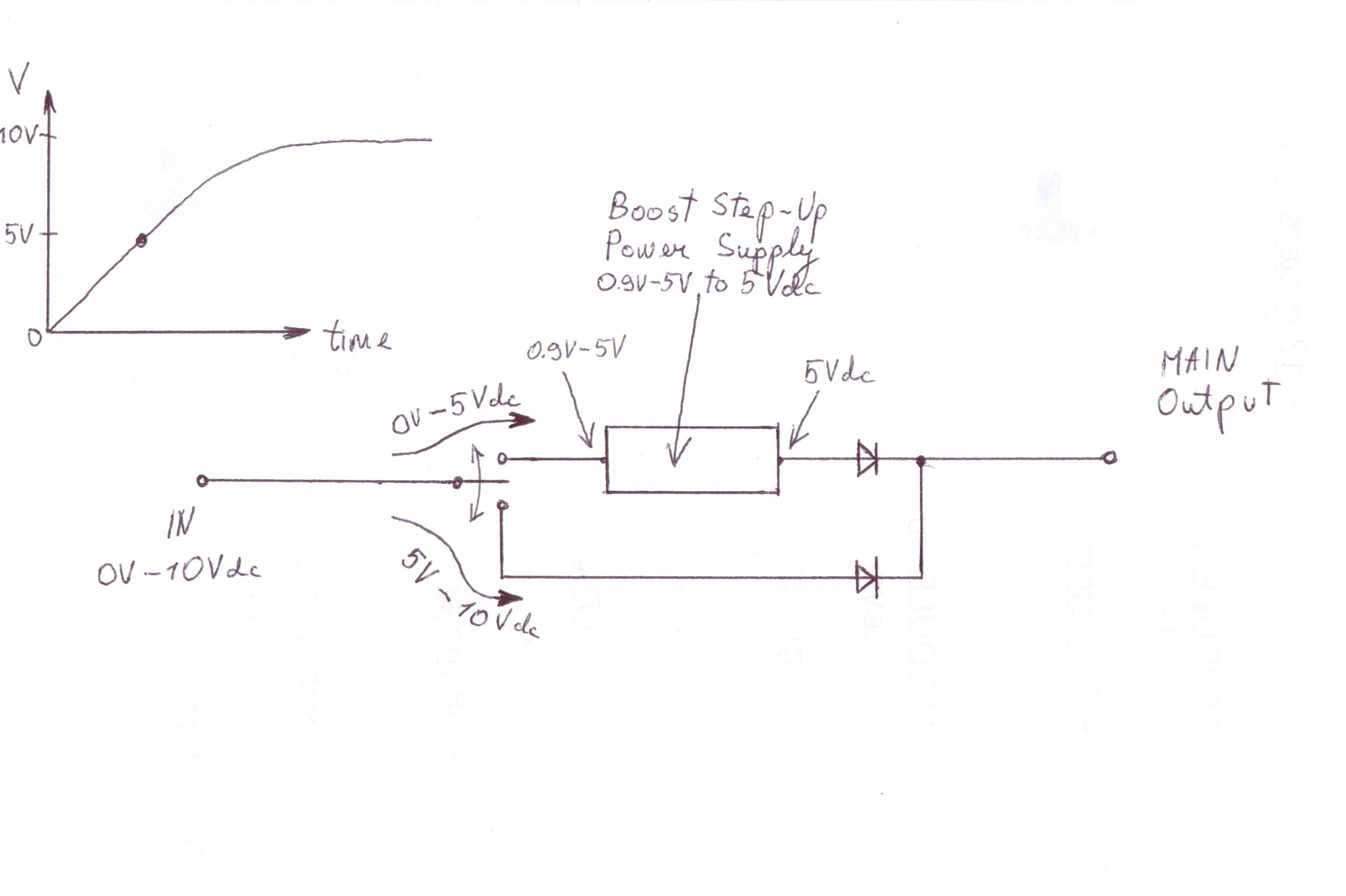
Hi guys, I would really appreciate if someone could give me advice on how to build circuit for this case. On my circuit input I have slowly arising voltage from 0V to 10V, and on my circuit I have 2 outputs. When input has 0V-5V, first output has to be active, but when voltage rises from 5V-10V, first output has to deactivate and second output become active. And vice versa, when voltage decreasing to less than 5V, second output has to deactivate and first become active.
5V is the point where output changes, depending on voltage.
I was thinking to use 5V or 6V relay which gets active when voltage gets close to 5V. But relay coil will always use energy, which is not good in my case, as I need as much as possible voltage and current on outputs. Can you help to project switching between two outputs using transistors or comparators circuit? Thanks in advance.