Continue to Site

Welcome to EDAboard.com

Welcome to our site! EDAboard.com is an international Electronics Discussion Forum focused on EDA software, circuits, schematics, books, theory, papers, asic, pld, 8051, DSP, Network, RF, Analog Design, PCB, Service Manuals... and a whole lot more! To participate you need to register. Registration is free. Click here to register now.

Switch Cap Integrator... Is the clock phase Important! Why gain is not 1?

Status
Not open for further replies.

Adam12

Newbie level 3
Joined
Jun 23, 2015
Messages
4
Helped
0
Reputation
0
Reaction score
0
Trophy points
1
Activity points
48
Hello there,

I am a newbie here,

Can you experts please let me know in a Switch-Cap integrator like the one in the below pic, what thing determines the MAXIMUM clock frequency the circuit can go?

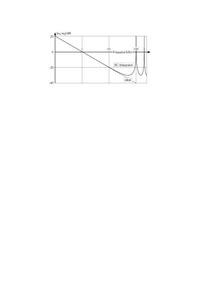
I deigned a continuous integrator with the input frequency of 600kHz (and the gain of 1), and then designed its equivalent Switch-Cap integrator... I selected the clock frequency to be at 40X (ie 24MHz)... I noticed that at 24MHz the gain is not exactly 1 for the switch cap, but it is less than that, and I noticed that the phase of the "Clock Frequency" is "93" degree! I then tried to reduced the input frequency to 100kHz and the clock to 4MHz, then I saw that the gain of the SC integrator changed to what I expected (ie 1) and the clock phase phase also changed to 90 degree... So whats wrong here? What causes the clock frequency to go to 93 degree at 24MHz?

Thank you so much or any help.
 

Attachments

  • SwitchedCap.gif
    SwitchedCap.gif
    6.8 KB · Views: 80

I don't even understand what's 90 degree for a two-phase clock. I would expect 0 and 180 degree nominal phases.

At least some explanation needed. How do you analyze the circuit? Which tool reports the said 93 degree pahse?

Generally speaking, it's a property of your clock generation circuit, not the SC filter itself.
 

Thank for your input...

Well cause the clock signal goes inside the op-amp, so I took a look at the frequency response and the phase of the SC integrator using the HSPICE software.... I even tried to connect a frequency signal equal to the clock one to to the continuous one to see the output frequency response and phase...
I noticed that when the clock freq is almost 90 degree, the output gain is what I expect.. but at higher frequencies were the phase was changed to say 93 or more the gain was less than what I expected!!

- - - Updated - - -

Well please let me explain more..

I designed a continuous integrator and then I converted it to a SC one by changing the R to its equivalent SC one using this:
C=1/(Fclic*R)...
The gain of my continuous integrator was 1, so I expected a gain of 1 from the SC one as well.... But I noticed that the gain of the SC integrator is less than its continuous equivalent one!!! I tried to investigate the problem by looking at the input-output signals/phases and freq response... I finally noticed that when the clock freq is more than say 10MHz I see the gain problem to happen... but when it is less than 7MHz the gain is just like what I expect (ie 1)... the Fclock in all my test was 40 times higher than the input freq... So it came to my mind that maybe there is a relationship between the clock freq and the output gain of the SC integrators... As I said, I tried to watch the output response (the freq response) and the phase by connecting a 10MHz and then a 7MHz signal to the input of the continuous integrator (I did this for the SC integrator too, when the 10MHz and the &MHz were used as the clock)... I noticed that the the phase response is not 90 degree when the signal freq is 10MHz or higher... So I came to the conclusion that maybe the problem of the gain difference I mentioned is due to using a high frequency for the clock which causes the phase of the clock signal to be changed...

So why I don't see the gain of "1" in SC integrator at higher frequencies while it is an equivalent circuit of the continuous integrator?
How far the clock frequency can go in a switch Cap integrator?

Thanks for any help...

P.S, My tests were done using both HSPICE and PSPICE software...
 
Last edited:

So why I don't see the gain of "1" in SC integrator at higher frequencies while it is an equivalent circuit of the continuous integrator?

Just for clarification:
* An (analog, ideal) integrator has a "gain" which continuously decreases with rising frequencies (slope -20dB/dec). So - why do you expect a gain of "1"?
* An S/C integrator is not an "equivalent" circuit of the analog integrator. It only can approximate this function within a limited frequency range.
 

All switches have a series resistance and the parallel capacitance determines a break point in frequency response and phase begins to shift one decade below this. The ratio of ESR of caps to switch RdsOn also affects gain reduction as you dump the capacitance.

Ceramic caps also have a memory effect so NP0 type are better than the rest and film caps are better for ESR than ceramic but worse for tolerance. Your switches will also have capacitance Coss , so choose them wisely as well which increases as RdsOn decreases.
 

Just for clarification:
* An (analog, ideal) integrator has a "gain" which continuously decreases with rising frequencies (slope -20dB/dec). So - why do you expect a gain of "1"?
* An S/C integrator is not an "equivalent" circuit of the analog integrator. It only can approximate this function within a limited frequency range.

Thanks for all inputs....


When everything including the op-amp itself and the C2 (C feedback) are the same in both the continuous and SC integrators and you use the formula (Cin=1/(fclk*Rin), where Rin is the the input R of the continuous integrator then I believe both continuous and SC integrator are the same and should have the same gain for a similar input frequency... Am I wrong? If so, why I see the SC integrator has the same gain as the continuous for lower clock frequencies (while both circuits are equivalent with the same input frequency)?
 

Thanks for all inputs....


When everything including the op-amp itself and the C2 (C feedback) are the same in both the continuous and SC integrators and you use the formula (Cin=1/(fclk*Rin), where Rin is the the input R of the continuous integrator then I believe both continuous and SC integrator are the same and should have the same gain for a similar input frequency... Am I wrong?

Yes - sorry, you are wrong.
The obvious reason is that all S/C circuits are sampled data systems and, thus, follow the rules of Digital Signal Processing.
As a consequence, transfer functions of S/C circuits are defined in the z-domain (and not in the s-domain like analog systems). Typically, the transfer function shows periodic repetitions.

For this reason, the clock frequency must be much larger than the used frequency range (at least factor 50...100).
Parasitic influences (finite switch resistance, ESR of capacitors) are parasitics only and will cause some additional errors, but they do not cause any systematic application limitations.
 
Last edited:

See attachement: Difference between an analog integrator and S/C integrator. Sorry for the bad quality (I was not allowed to add a pdf doc; I don`t know why!).


I forgot to mention: Clock frequency 100 kHz.
 

Status
Not open for further replies.

Part and Inventory Search

Welcome to EDABoard.com

Sponsor

Back
Top