Continue to Site

Welcome to EDAboard.com

Welcome to our site! EDAboard.com is an international Electronics Discussion Forum focused on EDA software, circuits, schematics, books, theory, papers, asic, pld, 8051, DSP, Network, RF, Analog Design, PCB, Service Manuals... and a whole lot more! To participate you need to register. Registration is free. Click here to register now.

Suggestions for Low power GSM burglar alarm

Status
Not open for further replies.

johanfo

Junior Member level 1
Joined
Jan 19, 2012
Messages
18
Helped
0
Reputation
0
Reaction score
0
Trophy points
1,281
Activity points
1,450
Hi,

I have the following problem to solve. I have a storeage room 50m from my apartment, which I would like to have a simple alarm system which notifies me by SMS when triggered. Since this room has no power, the system's power source will have to be battery, and hence a very "low power" solution.

My design goes like this:
* A PCB board with a very low power circuit that monitors a magnetic switch (the alarm trigger). For zero power consumption, the system could be completely dead and only started when the switch triggers it.
* A GSM module, which will start-up when triggered, and notify me by SMS

In stage 2, I could (but this is more complicated):
* Make the system ring an alarm by responding to the alarm-sms.

My questions to you is:
* What kind of components would you use for this (pic, gsm module)? Take cost and simplicity into consideration.
* Do you have any suggestions, ideas or improvements for this project?

best regards
JF
 

Hi, and Welcome to Edaboard,

This is very simple and useful SMS alarm. Cover 5 zone/sensors. You can build multiple of thise if you need to cover more sensors/zones.
Every senzor SMS message can be programmed with some text what you define.
This works with Siemens phones with AT command support. Phones can be older and very cheap (about 2-4eur), just buy new battery and put into them if needed. Siemens with AT commands like S25, S35, S45, S55, C10, C35, C45, C55, C56, C60, C65, M35, M50, ME45, MT50, SL45(i),....
Take in mind what is price for GSM modul and other accessories need for GSM module.


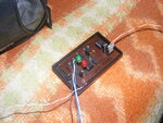
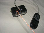
Picture of my device :

Phone charging over sms alarm device, sms alarm works over leadacid battery 12V 7A, which is charged over small solar cells, which I took from several cheap garden solar lamps (I make my cheap solar panel). For my second version I plan to replace leadacid 12V battery with lithium battery, and use smaller number of solar cells for charging.
On this picture this is my first version, I make now smd version, very small, to be compacted into phone battery space (of course battery goes out, and power will be supplied from outside of phone - in second SMD version).
Text of each of five SMS messages and phone number programmed via PC with PDUSpy software and upload to device with smsuploader software. Connection to PC is done over simple interface.

DSCF0018.JPG DSCF0011.JPG


Circuit :

sms_alarm_shema.png


PC interface for device SMS text / phone number programming :

PC Interface.gif


This can be used to convert contacts of sensors NC to NO or reverse (on place of device NC you can put phototransistor and use cheap laser pointer 5mW from 100m and over distance to point on that phototransistor, when laser beam is breaked SMS goes into air) :

Senzor NC NO Connections (3 variants).jpg


For sensors you can attach anything you whant, I use lasers, reed relays, PIR sensors, smoke detectors, capacitive touch sensor,.....

On circuit showed speaker is only activated to say that connection between phone and device are lost (that parts is not required).


On this location you can find original files about SMS alarm :
GSM SMS alarm - Elektronika.ba

Similar project 4 relays/outputs which can be turned On/Off, and sense of 4 sensor states using SMS (this project use Nokia phones like 7110,6210,6310,...). This device get power direct from phone, no need for additional power supply for device :
GSM kontroler v2 - Elektronika.ba


Both tested and working great!!!

Also there is GSM Call Alarm which can be combined with this,.....


Note :

If you need to save power, consider usage of reed relays with magnets with NO state (reed relay is normally open, when door is open reed relay closes and give impuls to uC to send SMS on specified phone number).
GSM module needs more power to work then phone. Phone also have battery for working, which can give power to phone about five days - of course this depends from phone, but this phone will be only in standby state and will send sms only, that give more power to phone to prolong working time. Also GSM module have high price ranged from 30-50eur to 150eur and higher. GSM modules needs more power to works ranged from 200-300mA to 1A or even more.
If you plan to use PIR, smoke,... sensors you should see their need for power (about 20mA @12VDC).
 
Last edited:

Thanks for very interesting post! It is of great use!

Hi, and Welcome to Edaboard,
If you need to save power, consider usage of reed relays with magnets with NO state (reed relay is normally open, when door is open reed relay closes and give impuls to uC to send SMS on specified phone number).
GSM module needs more power to work then phone. Phone also have battery for working, which can give power to phone about five days - of course this depends from phone, but this phone will be only in standby state and will send sms only, that give more power to phone to prolong working time. Also GSM module have high price ranged from 30-50eur to 150eur and higher. GSM modules needs more power to works ranged from 200-300mA to 1A or even more.
If you plan to use PIR, smoke,... sensors you should see their need for power (about 20mA @12VDC).
[/I]

I was planning on having a total power consumption so low, that the device would be self powered for at least one year, preferably more, on say ~4 AA batteries. The room to be surveilled is in the dark, so I'm out of luck with solar cells! To do that, I would have to power up the cellphone when activated. I'm also considering powering the gsm unit from the battery-pack, so that I don't need two types of batteries.

Do you see any problems with this?

best regards
JF
 

@JF... GSM modules are power hungry, i mean, when compared to rest of the electronics. Also driving relays requires good deal of energy.
Finally the sensors, based on type, may require good bit of power as well. Remember that many of your sensors are actually always-on, and only some are based on mechanical or EM switch. Driving all this with 4x AA batteries, isn't really feasible (AFAIK) given current day battery technology, i.e. for the duration you want this to run self-powered. Operation for few hours, with all those peripherals for 3-4 hours is feasible, but then with more peripherals, sensors etc., the run-time can come down drastically.

Note that you'd also be dealing with 5V and quite possibly 12V supply. Most of the PIR modules require 12V supply. If running off 4x AA's, you'd need a Charge-Pump to boost it up to 12V, but it might be really difficult to provide the kind of current needed for all this.

Of course, if you are willing to hook-up a large battery bank, especially Lithium batteries, this is achievable, but I get the feeling that you might also like this to be relatively economical / low-cost. Else, the cost of powering your device will far outweight the cost of the rest of this project. If you are okay with it, then it is not a problem.
 

You need power, small solar cell can be out of room, put on light, and with cable that transmit power to device inside.

I am afraid that you dont have needed enough power and voltage from ~4AA.

With 4AA you get 6V (alkaline) or 4,8V (NiMi). I think this is low.

Like I told in post #2, you can use reed relay with magnets to eliminate sensor power consuption (in this case no sesor power consuption, only main device consupt power).
 
Last edited:

@Jaychar88: The whole purpose of this project is to create a super-low power consumption GSM-alarm-device. As you point out, a lot of sensors are active (requires power) and I'm aware of that. This is why PIR-style sensors are not feasible. I'm looking into some kind of mechanical-switch attached to a door (which is the only way in), so the sensor is fully passive. By triggering this sensor, you power up the entire system (either from low power sleep, or completely cold) which then sends SMS.

By this design, I believe it is possible to create a "passive" alarmsystem with battery life of years, instead of hours (but correct me if I'm wrong). What does a Siemen phone use for Voltage? 7V/12V/14V?
Perhaps 2x9V batteries could be used. Again, I'm not looking for continuous operation her, only enough power to fire it up and send an SMS.

You need power, small solar cell can be out of room, put on light, and with cable that transmit power to device inside.
I am afraid that you dont have needed enough power and voltage from ~4AA.
With 4AA you get 6V (alkaline) or 4,8V (NiMi). I think this is low.

Unfortunately, the device will be to deep in the cellar to attach to any solar panels.
 

What does a Siemen phone use for Voltage? 7V/12V/14V?

Siemens use yours 3,6V battery. And device need 5V power supply.

Typical battery capacity of AA for alkaline is 2000mA and typical continuous current is 50mA.
But voltage when alkaline battery is new and full charged is 1,6xxV and when discharging voltage drop to 1,3V...

If you whant long period one year on small batteries, you must have device which is turned off totaly, and when some reed relay activate then this turn on device and send sms, after that again turned off.

When powering up device and phone, time is needed for arming system.


I think this is posible!!!
 
Last edited:

@JP

your passive monitoring, and activation using mechanical switch is a nice idea, but there are few things to keep in mind -

- time required by most uC's to startup ranges between 50-100ms (from power-on / reset)
- GSM modems will require the uC (once start up) to handshake, set up the AT-commands, etc., that too after the modem has registered to GSM network. The time it takes to do all that post a power-cycle can be in the order of several seconds.
- if you power-on all sensors, peripherals at the same time, immediately on startup, there would be a huge cold-start current draw, which your battery might find very hard to delivery, so you might want to space-out the sensor activation to overcome this.

given all the above, you'd see that passive sensors have the problem that they might actually miss critical events, especially if the events you are trying to detect, are momentary and happen too fast.

---------- Post added at 16:39 ---------- Previous post was at 16:35 ----------

@JP few questions -

- Are you sure that GSM phone works well in your cellar ? If the signal strength is too low (feeble) then module will transmit at max. power, thus draw more current as well.
- Is there a possibility that you could separate out the "detection" unit and the "transmission" units, s.t. transmission unit is somewhere where possibility of grid-power, or other recurrently charging (s.a. using photovoltaics) exists ? That way, you can solve the power problem.
 

Most of the PIR modules require 12V supply. If running off 4x AA's, you'd need a Charge-Pump to boost it up to 12V, but it might be really difficult to provide the kind of current needed for all this.

I was looking at this link **broken link removed** , which claims less than 10 microAmps! (how do thay do it?) With a batterysource of just 500mAh @3V this would power such a device for 500/0.01 = 50.000 hours?! Seems crazy to me...
 

- Are you sure that GSM phone works well in your cellar ? If the signal strength is too low (feeble) then module will transmit at max. power, thus draw more current as well.

Phone works very nice, without any problem. Should I tell you that signal is good from basement of building full of armored concrete (second level underground). You must have good coverage of network.

Its just a regular cheap phone no need for expensive GSM modem/module, also which have power needs 500mA-1A.
Phone just send SMS message like sending SMS everyday in life. There is no need to searching for hot water.
 

your passive monitoring, and activation using mechanical switch is a nice idea, but there are few things to keep in mind -

- time required by most uC's to startup ranges between 50-100ms (from power-on / reset)
- GSM modems will require the uC (once start up) to handshake, set up the AT-commands, etc., that too after the modem has registered to GSM network. The time it takes to do all that post a power-cycle can be in the order of several seconds.
- if you power-on all sensors, peripherals at the same time, immediately on startup, there would be a huge cold-start current draw, which your battery might find very hard to delivery, so you might want to space-out the sensor activation to overcome this.

given all the above, you'd see that passive sensors have the problem that they might actually miss critical events, especially if the events you are trying to detect, are momentary and happen too fast.

- Startup time is not a huge issue. Yes, I agree that if the "burglar" knows the system, it is easy to deactivate. However, this is about protecting a cellar with some expensive bikes. Most likely burglar will be some drugie/criminal with little suspicion about a GSM-alarm system there. Even with a combined startuptime of 10 seconds, this system will make a huge difference! Actually, these 10 seconds would be quite useful for deactivating the alarm somehow myself. Don't want to get a lot of SMS every time I open the door myself :)
- About powering up. I only see 2 units that needs to be powered up. The central PIC, and the cellphone. In the basic design, there will only be one trigger-switch, attached to the door.

@JP few questions -

- Are you sure that GSM phone works well in your cellar ? If the signal strength is too low (feeble) then module will transmit at max. power, thus draw more current as well.
- Is there a possibility that you could separate out the "detection" unit and the "transmission" units, s.t. transmission unit is somewhere where possibility of grid-power, or other recurrently charging (s.a. using photovoltaics) exists ? That way, you can solve the power problem.

Quite sure. My Iphone 3GS works there at least, so I believe a Siemens should as well, but you never know :/

- Is there a possibility that you could separate out the "detection" unit and the "transmission" units, s.t. transmission unit is somewhere where possibility of grid-power, or other recurrently charging (s.a. using photovoltaics) exists ? That way, you can solve the power problem.
Unfortunately no. This alarm has to be 100% self powered.
 
Last edited:

I using several years Siemens phone with SMS alarm showed in post #2, and no problem !!!.

I using this on multiple places even in car.

Works like charm! :wink:
 

I was looking at this link **broken link removed** , which claims less than 10 microAmps! (how do thay do it?) With a batterysource of just 500mAh @3V this would power such a device for 500/0.01 = 50.000 hours?! Seems crazy to me...

Great find. I had to triple-check that site to make sure that I am not reading "micro" when it should say "milli". Honestly, no idea how they got it so low. This is the first PIR device, I've seen running at 3VDC. OTOH, **broken link removed** seems to have a current drain that I am certainly more familiar with.
 

Hi,

I bought a Siemens C45 phone on ebay for this project, and received it today. Now I believe that I have made a rookie mistake. It is "locked" 8-O ,seller didn't mention it. My mistake for not asking of course...

Does anybody know how to unlock that model?

Searched the net without luck. Now, I'm thinking that it just might be easier to buy another phone, this time "unlocked"

JF
 

I belive Fortuna doesn't smile to me on this project! As I described earlier, my first Siemens phone I bought was "locked", with no simple way of unlocking it. So I bougt a new one, Siemens C65. However, now I start to wonder wether this phone doesn't use regular TTL(?) logic on its TX/RX, but rather USB(!).

The reason why I believe this is that, first I can't send AT commands to it. (I'm using putty), and second is this source Siemens A52, A55, A56, A60, A65, AL21, AX75, AX72, C55, C56, C60, C62, C65, C70, C75, CF62, CF75, CFX65, CL75, CT56, CX65, CX70, CX75, CXT65, CXT70, CXV65, CXV70, M55, M65, MC60, M75, MT55, ME75, S55, S56, S57, S65, S75, SL5C, SL55, SL56, SL65, SK65, , which seem to state that the D+/D- of the C65.

Now, increadably, I did buy a serial (com port style) data wire on ebay that claims to be Siemens C65 compatible. In order for such a wire to work, it has to have some RS232 to USB logic in the plug and act as a host, but is this really plausable?!

Serial cable: (says Siemens C65 compatible in the ad)
**broken link removed**

But I ALSO found regular USB wires! I'm confused :(

USB cable:
**broken link removed**


So my question to the community: Have I messed up again? Next time I buy one I need to be damn sure! :)
 

Iterface for connecting SMS alarm to PC, only needed to use when programming SMS messages texts :

PC Interface.gif


The same can be used to interface phone.


Siemens C65 can send AT commands, 100% its confirmed, I have that phone on one of SMS alarm.


See this AT command set for Siemens phones :
 

Attachments

  • s25_atc_commandset_v10.pdf
    272.6 KB · Views: 130

Iterface for connecting SMS alarm to PC, only needed to use when programming SMS messages texts :
View attachment 70437
The same can be used to interface phone.
Siemens C65 can send AT commands, 100% its confirmed, I have that phone on one of SMS alarm.
See this AT command set for Siemens phones :


Yes, you are absolutely right! I confirmed it yesterday by using putty with a serial-data cable. Further, I also attached my scope to the datawires which verified that the protocol was ~3V TTL, idle high.

I managed to send a lot of different commnds through putty using the data cable, and got proper responses. However, when I issued the AT+CMGS=19, and then pressed enter in order to insert the PDU data, the entire phone crashed! Very strange! Could be a phone problem, data interface problem, or data protocol problem. I don't know.

I have little hope that someone here would know what is wrong, but if you have any ideas, please let me know.

best regards
JF
 

An update on my project:

I finally got it working. I learned two important things:
1) Siemens phones shuts automatically down if the voltage is too high: > ~4v
2) In order for a Siemens C65 to accept data, the CTS (pin 5) need to be shorted to ground.

This is my current setup:

Untitled.png

Still, there is a lot of work to be done:'

* Move the logic from PicAxe to pure PIC-code
* Make the trigger logic. I believe I will use a magnetic switch of some kind.
* Make logic so that if I accept the call from the alarmsystem, I trigger the sound alarm. If I reject, nothing happens.
* Interface the keyboard of the mobile phone. This is in order to be able to switch it on, and to press a specific button to confirm that I indeed want to switch it on. I have disabled the pin-code check in the startup.
* Transform voltage from 6V to 3.7V for the mobile. The phone needs 3.7V, and I tried to run it from 3 x AAA batteries (4.5V) with two diodes in between to lower the voltage. However, when the phone started to draw power during startup, it instantly shut down. Alkaline batteries drops to much under load! Solution: Use a voltage regulator to lover the voltage from 6V to 3.7V. My estimates are that 6V time 0.7 A = 4,2 W - efficiency loss, should be enough to run it without any fuss. If that is not enough, I will have to add more batteries or shift to C/D -cells
* Make sure that the entire system, in its idle state, can run for minimum 4 years without battery change. Of course, if triggered this will affect lifetime significantly.

Finally, I have some questions for all the smart people out there:
* What is the best way to transform 6V battery power to 3.7V constant power, with minimal efficiency loss.
* What software do you use for schematics? I have tries some, but don't feel very comfortable with them?! Is there a "Paint shop pro" for electronics design? That is cheap and good :)

best regards
JF
 

Status
Not open for further replies.

Part and Inventory Search

Welcome to EDABoard.com

Sponsor

Back
Top