Continue to Site

Welcome to EDAboard.com

Welcome to our site! EDAboard.com is an international Electronics Discussion Forum focused on EDA software, circuits, schematics, books, theory, papers, asic, pld, 8051, DSP, Network, RF, Analog Design, PCB, Service Manuals... and a whole lot more! To participate you need to register. Registration is free. Click here to register now.

Stackup problem in HyperLynx

Status
Not open for further replies.

mostafanfs

Member level 1
Joined
Aug 2, 2012
Messages
40
Helped
0
Reputation
0
Reaction score
0
Trophy points
1,286
Activity points
1,611
Hi
when I run HyperLynx BoardSim it asks for considering a plane layer and based on what it says it seems it's calculations and simulations are all based on existence of plane layer(s).

What I have to do ? My PCB Layout has only 2 simple layers.Top Layer And Bottom Layer. So by opening board this window come up and you can see the warning. It seems BoardSim needs reference layers that can carry return currents as you can see in Hint section.
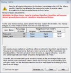
plane.PNG

I even designed stackup based of my plan in Stackup Editor.
So I think all of my simulations and Resistor Termination calculations was wrong. Am I right ?
I cant just add a plane layer because there is not any plane layer.

Please someone explain what exactly this window says and what should I do ?
What does it mean by that WARNING ?
I really need to understand this. Thank you
 
Last edited:

Firstly could you provide somedetails of the speed of signals and rise times of same on your PCB.
As far as I am aware hyperlynxis for high speed signal integrity, if you dont have a return plane the software cannot calculate the impedances and thus cannot realy calculate do the field solver calculations.
 
the mentor hyperlynx software always assume a complete plane for the calculations ( at least 3 times the trace width ). in your stackup you don have any. so all the calculations are made for traces crossing a large plane discontinuity. you may want to use a different simulation tool, if there are no planes at all.

here is a free one : Quite Universal Circuit Simulator
 
Firstly could you provide somedetails of the speed of signals and rise times of same on your PCB.
As far as I am aware hyperlynxis for high speed signal integrity, if you dont have a return plane the software cannot calculate the impedances and thus cannot realy calculate do the field solver calculations.

Actually I was just trying to learn how to work with HyperLynx. At now my board isn't a High speed digital board. But I have plan to built a high speed ADC+FPGA board.
Thanks for your post. Could you explain "return plane" expression? Why does it mean exactly and why does it matter to us ?
Also could you introduce a PDF or book that I can use to understand these SI subjects ?

- - - Updated - - -


the mentor hyperlynx software always assume a complete plane for the calculations ( at least 3 times the trace width ). in your stackup you don have any. so all the calculations are made for traces crossing a large plane discontinuity. you may want to use a different simulation tool, if there are no planes at all.

here is a free one : Quite Universal Circuit Simulator

So you mean I have to consider a plane for my design?
and it would be connected to 'GND'. Right ?
"return plane" means GND net ?
And what are you mean by " at least 3 times the trace width " ? I didn't follow


As I said I have 2 layers: Top layer and bottom layer.
How about considering the Bottom Layer as a Plane Layer in that warning window or in Stackup Editor ?
Because I didn't use this layer as a signal layer except for routing Power Supply nets like +3.3V +1.2V +2.5V +3.3VLAN and a few couple more nets.
As you can see in the attached PDF of my Bottom Layer PCB you can see that most percentage of that is connected to GND, I think it would be work almost like a plane !
What do you think ? Does it have to be like Solid plane ?
 

Attachments

  • Control_PCB_1_3.pdf
    593.1 KB · Views: 120
Last edited:

if you consider the bottom layer as a plane then you need to change this in the stackup editor. use the drop down menu to change it form signal to plane.
please re read the hint that is given in that message box.

mentor assume that the GND plane is a solid plane, without any discontinuities.
 
The return path and understanding it (andd thus how current does flow) is critical to high speed PCB layout. Electrons do not run round the track like a train, the return current is instanteneous and at speeds from 1MHz up follows the path of least inductance. As I have said understanding this is critical for todays PCB's, the follwoing should be a start.
**broken link removed**

The text file is my standard list of PCB related links for people to peruse. The return path is not always the ground plane, power planes will also act as a return path.
 

Attachments

  • PCB related links.txt
    5 KB · Views: 109
Choosing SI Oscilloscope Frequency

Really thank you guys
I was looking into HyperLynx and this question came up

When running SI Oscilloscope there is two option : Edge And Oscillator. Which one is better to choose ?
I think Oscilloscope is much better clear obviously. But what number should I enter as frequency ?
What are the parameters that I should consider when entering frequensy ? Does it really matter ?
 

I wouldimagine edge refers to the rise time of your signals, this is the ultimate pointer to whether a design is high speed.
 
oscillator is generally used for clock signals. use the frequency of your clock on board.

It doesn't make sense at all. cause all nets in a design dont have a same frequency. I think I should somehow geuss or approximate the working frequency of that net and see results for that frequency. Right ?

Plus I figured out it doesn't seem calculations are based on frequency. as it should be. for example termination resistor calculations is not related to the frequency. also other simulations like Crosstalk and so on ...
How is it that termination resistor calculation is not related to the frequency ?
 
Last edited:

High Frequency ... How much ?

I'm curious how much frequency at least do you guys mean by High Speed or High Frequency in your posts ??
Is it a specific number?
Cause you guys said before that hyperlynx is for high speed signal integrity ...

I'm trying to make a 65 MSPS ADC Board using FPGA. Is it a high frequency design?
Do I have to consider a Ground and Power Plane ?
Thank you
 
Last edited:

Yes
Yes and
Yes
Actually the rise time of your signals (not clock frequency) determines whether high speed design rules have to be followed. To make my life simple I consider ALL digital designs to be critical so follow best practice (high speed design!) on ALL designs I do.
 
I'm back !
How do you guys use HyplerLynx ?
You know what I mean ?
I mean I use HyperLynx and it suggests a termination topology using Terminator Wizard (most of the times Series Resistor Termination) and it gives me a terminator resistor value
But I had never seen such resistors in any product or board allover the world!
If it's used, they just used usuall 33 or 47 Ohm resistors in FPGA and DSP Boards. While the HyperLynx suggests different values like from 20 Ohm to 500 Ohm

So I'm gonna ask you one more time: How do you guys use HyplerLynx ?
Is such softwares like HyperLynx really practical ?
 

source-series termination is calculated from output impedance and resistor to match the trace impedance. Rd + Rs = Zo
A lot of people use hyperlynx. It is an excellent tool. if you want to know how to use it Mentor has online courses.
there are also a couple of videos on their site.
 
Thank you. I have found a good tutorial for Signal Integrity using HyperLynx
But still have found nothing good for Power Integrity in HyperLynx and I dont know where to begin. All menus for this type of analysis are off in HyperLynx and I can just assign Power Nets in Edit Power-Supply Nets window (Setup -> Power Supplies)
What is the next step ? How can I setup my board to do Power Integrity ?
Is there a good tutorial or Video for this ?
 

Just to answer an earlier question:
How is it that termination resistor calculation is not related to the frequency ?
termination resistors (or series ones) are chosen to control the characteristic impedance of the line, this is unrelated to a greater extent to frequency.
 
Status
Not open for further replies.

Part and Inventory Search

Welcome to EDABoard.com

Sponsor

Back
Top