Continue to Site

Welcome to EDAboard.com

Welcome to our site! EDAboard.com is an international Electronics Discussion Forum focused on EDA software, circuits, schematics, books, theory, papers, asic, pld, 8051, DSP, Network, RF, Analog Design, PCB, Service Manuals... and a whole lot more! To participate you need to register. Registration is free. Click here to register now.

Stability of feedback loop

Status
Not open for further replies.

fala

Full Member level 5
Joined
Sep 18, 2005
Messages
249
Helped
19
Reputation
38
Reaction score
4
Trophy points
1,298
Activity points
3,569
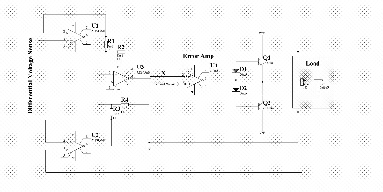
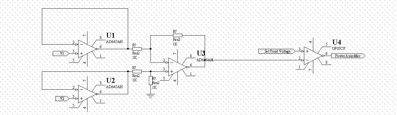
Hello, I have a circuit that measures voltage differentially and then by feeding the measured voltage to an error amplifier that has a fixed voltage at its non inverting pin completes the feedback loop of error amplifier. My question is what should I do to prevent instability of feed back loop because there are three opamps in the feedback path so if each opamp shift 60 degrees it means 180 degree shift and resonance. The load can have some capacitance and the capacitance of load is not known to me. So how should I stabilize the feedback loop. Input opamps should be low Ib fet opamps.
Should I put low pass filter between U3, U4??? Thank you very much
97_1157042112.jpg
 

fala,
There is no feedback path shown, except for the local feedback around the individual stages U1, U2, U3. How does the output of the error amplifier affect the differential inputs at V1, V2 at U1, U2. Please complete the schematic to show the overall feedback path. In general, you must provide compensation so that the phase shift at the point where the open loop gain goes to zero is less than 180 degrees. Anything more that about 135 degrees will result in excessive overshoot.
Regards,
Kral
 

Thanks Karl, Sorry if I was unclear, I posted a new schematic as you can see differential voltmeter u1,2,3 senses the voltage that is applied by error amp u4 & power amp and then voltage feedbacks to the error amp. As I said load capacitance is unknown to me and can be anywhere from pF to uF range.; should I put a low pass filter at point X in the schematic? How can I minimize the phase shift by u1,2,3? Set point voltage may change so I would like to have the widest bandwidth possible so that my error amp dose not oscillates. Thanks again
94_1157052973.jpg
 

Hello, U2 is driven by a ground (in the + port), so U2 is not really fedback globally.
Also, how the diodes D1 and D2 are biased?
 

you can insert a current sensor in the loop, then run stb simulation in
the spectre and check the phase and gain margin.
 

Hi,
To check for the stability of the feeback circuit you need to break the loop.
For that place a 'iprobe' or 'DMCM' from analoglib and add it to the feedback path.
Then run STB analysis and it will give the gian and the phase margin also the gain and the phase plot, from which you can get the stability of your system.

Thanks
Shaikh Sarfraz
 

wpchan05:
D1 & D2 sgould be biased by unshown resistors u2 has a very obvious feedback, I don't get you?
gte582w & shaikhsarfraz:
load capacitance can be anywhere from pF to uF range, so I guess I will meet instability anyway and the question I've asked is how it can be tackled?
how should I select opamps? should I put low pass filters at point X?
thank you
 

first - i don't get the point of the diodes. If D1 is forward biased, then it will be attempting to pull current out of the base of Q1 which is an NPN. With D2 forward biased, you're trying to push current into the base of a PNP. What's up with that?

To understand whether this system needs to be compensated in any mannr, you need to obtain the gain equations for the open loop model. Once you know the poles and zeroes of your system, then you can determine stability/instability. If unstable, then either use nyquist or bode and figure out where you need to place poles/zeroes and then close the loop.
 

fala said:
wpchan05:
D1 & D2 sgould be biased by unshown resistors u2 has a very obvious feedback, I don't get you?
gte582w & shaikhsarfraz:
load capacitance can be anywhere from pF to uF range, so I guess I will meet instability anyway and the question I've asked is how it can be tackled?
how should I select opamps? should I put low pass filters at point X?
thank you

U2 definitely has local feedback, but not global feedback. Thus, U2 will not degrade any stability as far as the signal path is concerned. Moreover, the ground symbol connected to the positive terminal of U2 makes me feel that U2 has nothing to do with signal processing (U2 may provde dc bias only, but what is the point of using opamp)
 

out to lunch:
D1&D2, Q1&Q2 and bias resistors that has not been shown are a class AB amplifier.
about finding poles and zeros, There are some explanation about how to find them in simple feedback systems in Electronic text books that I have but the information can't be applied to analyze a complex circuit like above. there is no information about how to compensate a circuit with multiple opamps. can you at least kindly reference to a text(preferably available online) that covers the issue so by reading that I be able to solve the problem, please.
wpchan05: u1&u2&u3 are a standard diff amplifier, there is nothing unusual about them. my problem is how I can prevent the system from instability. how I may have the widest bandwidth for let's say 1uF load. where I should put poles and zeros.
I will be grateful if someone at least refers me to a useful text so I can find the answers.
 

I studied some articles and I found out that by placing a zero (a high pass filter) I can induce +45 degree shift. Of course if place of zero is inappropriate it can introduce instability rather that stability but the problem is if I put zeros then DC will be filtered out and I don't want this to happen. How can I do this?
 

Status
Not open for further replies.

Similar threads

Part and Inventory Search

Welcome to EDABoard.com

Sponsor

Back
Top