Continue to Site

Welcome to EDAboard.com

Welcome to our site! EDAboard.com is an international Electronics Discussion Forum focused on EDA software, circuits, schematics, books, theory, papers, asic, pld, 8051, DSP, Network, RF, Analog Design, PCB, Service Manuals... and a whole lot more! To participate you need to register. Registration is free. Click here to register now.

[PIC] SPWM Pure Sine Wave Inverter error

Status
Not open for further replies.

Johnnygsh

Newbie level 3
Joined
Jan 14, 2014
Messages
4
Helped
0
Reputation
0
Reaction score
0
Trophy points
1
Activity points
36
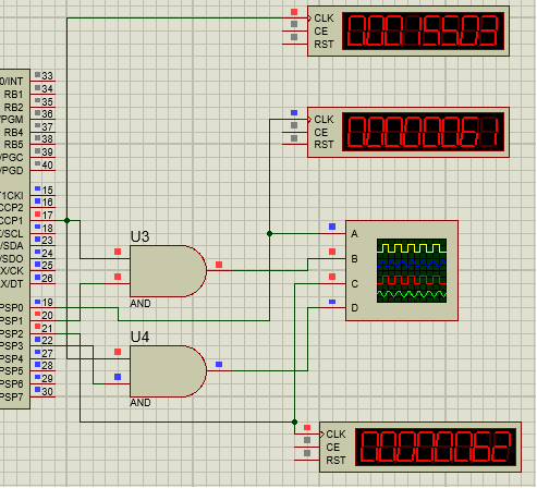
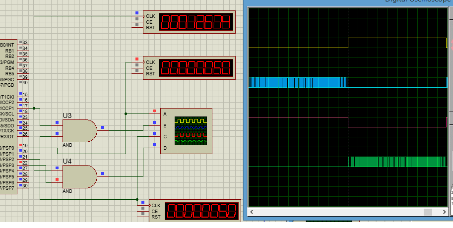
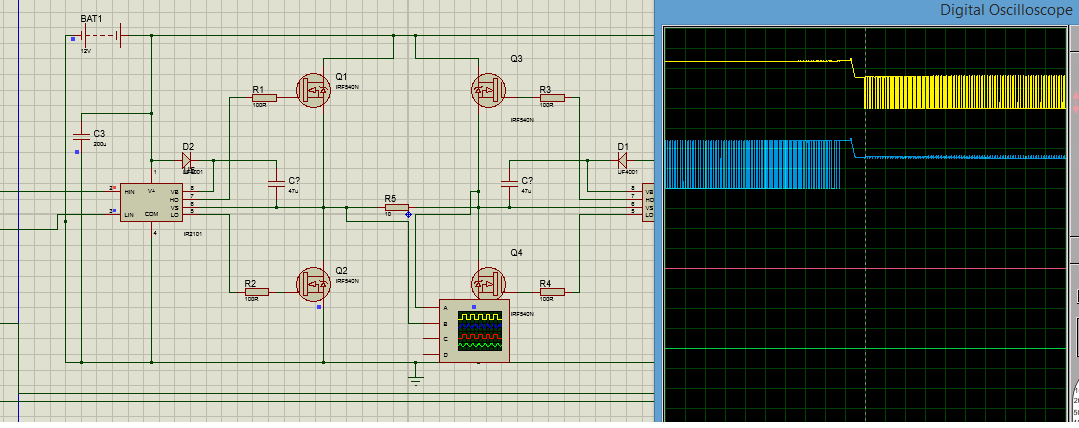
I have designed a pure sine wave inverter using a H bridge design and using SPWM created from microconroller, PIC16F877. I have attached the proteus simulation files along with the mikroc code, not written by me but taken from another site. I receive an error when pressing play to simulate the design and would like to know if anyone can help me in rectifying this error please.
 

Attachments

  • Files.rar
    54.3 KB · Views: 227

It simulated well.

5401285100_1390083271.png


with 3.27MHz crystal.


I appreciate the you have taken the time to respond and help me ALERTLINKS. However if you open up the PIC_SPWM_HBRIDGE_TEST proteus file and simulate it you will encounter the following errors shown in the image below. From the pic side everything seems to be working as you have demonstrated with your image you uploaded. Do you have any thoughts and what these errors can be caused from?? Any help will be appreciated

Simulation_Error.png

Simulation_Design.png

- - - Updated - - -

My apologises on not saying this earlier, but I am attempting to design a 115V rms 60hz signal power inverter system and I am trying to simulate the H Bridge design along with the PIC16F877, which performs Sinusoidal Pulse Width Modulation. But as can seen by my previous post 2 mins ago I am obtaining some simulation errors and would appreciate any assistance.
 

Thank you for getting it to work ALERTLINKS, I was wondering if you would not mind telling me the slight adjustments you made to the circuit to allow for it to work?? It will be greatly appreciated.
 

Actually it is the problem with the software when it is hard to calculate at certain node rapidly otherwise circuit will perform O.K. in real hardware. I only increased load at output. Try changing from 1K to 10 ohm.
 

Thanks very much ALERTLINKS, I have changed the load as you suggested and it has simulated. It sometimes simulates for a few seconds, sometimes longer and then automatically stops, but I will go on your assumption that on hardware it should work properly until I have actually built it on hardware.

I was also wondering if you could help in explaining the graph that the osciollsope gives when it is simulated. I have attached the results of the oscilloscope below.
Oscillscope_Results.jpg

Some Questions that I have are:
1. Why are not the both graphs the same since the H bridge topology is symmetrical?
2. Why is the fundamental period is 40ms which would give a fundamental frequency of 25Hz since the PIC was programmed to output a fundamental frequency of 60Hz?
 

Status
Not open for further replies.

Similar threads

Part and Inventory Search

Welcome to EDABoard.com

Sponsor

Back
Top