imranahmed
Advanced Member level 3
- Joined
- Dec 4, 2011
- Messages
- 817
- Helped
- 3
- Reputation
- 6
- Reaction score
- 3
- Trophy points
- 1,298
- Location
- Karachi,Pakistan
- Activity points
- 6,493
Hi all,
I have code for SPWM and it has Atmega328 Timer1 Mode 8 Phase and Frequency Correct PWM Mode it is working well with deadtime but I want some difference.
I require complimentary PWM output I done it output is complimentary output of PWM. Both complimentary outputs of PWM went to LOW after values read from lookUp table
I want OCR1A should always be HIGH after PWM pulses and OCR1B should goes to LOW after PWM pulses or lookUp table.
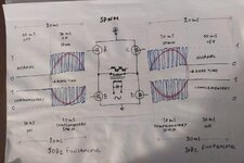
As in attached picture I want to generate PWM like in picture.
For Positive cycle, Mosfet A is OFF Mosfet B is ON, Mosfet C Normal PWM and Mosfet D is complimentary PWM.
For Negative cycle, Mosfet C is OFF Mosfet D is ON, Mosfet A Normal PWM and Mosfet B is complimentary PWM.
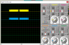
I am generating now as picture with oscilloscope but I want as picture with paper work.
I have code for SPWM and it has Atmega328 Timer1 Mode 8 Phase and Frequency Correct PWM Mode it is working well with deadtime but I want some difference.
I require complimentary PWM output I done it output is complimentary output of PWM. Both complimentary outputs of PWM went to LOW after values read from lookUp table
I want OCR1A should always be HIGH after PWM pulses and OCR1B should goes to LOW after PWM pulses or lookUp table.
As in attached picture I want to generate PWM like in picture.
For Positive cycle, Mosfet A is OFF Mosfet B is ON, Mosfet C Normal PWM and Mosfet D is complimentary PWM.
For Negative cycle, Mosfet C is OFF Mosfet D is ON, Mosfet A Normal PWM and Mosfet B is complimentary PWM.
I am generating now as picture with oscilloscope but I want as picture with paper work.
Code:
#define MAX_COUNT 500    // (16 MHz / SW_FREQ) / 2
#define NO_OF_PULSES 160 // 16 kHz / 50 Hz = 320; 320 / 2 = 160 pulses in one half-cycle

int lookUp[NO_OF_PULSES] = {500, 490, 480, 471, 461, 451, 441, 431, 422, 412,
                            402, 393, 383, 374, 364, 355, 345, 336, 327, 318, 309, 300, 291,
                            282, 273, 264, 256, 247, 239, 230, 222, 214, 206, 198, 190, 183,
                            175, 168, 161, 153, 146, 140, 133, 126, 120, 113, 107, 101, 95,
                            90, 84, 79, 74, 69, 64, 59, 54, 50, 46, 42, 38, 34, 31, 28, 24,
                            22, 19, 16, 14, 12, 10, 8, 6, 5, 3, 2, 2, 1, 0, 0, 0, 0, 0, 1,
                            2, 2, 3, 5, 6, 8, 10, 12, 14, 16, 19, 22, 24, 28, 31, 34, 38,
                            42, 46, 50, 54, 59, 64, 69, 74, 79, 84, 90, 95, 101, 107, 113,
                            120, 126, 133, 140, 146, 153, 161, 168, 175, 183, 190, 198, 206,
                            214, 222, 230, 239, 247, 256, 264, 273, 282, 291, 300, 309, 318,
                            327, 336, 345, 355, 364, 374, 383, 393, 402, 412, 422, 431, 441,
                            451, 461, 471, 480, 490
                           };

volatile bool positiveHalf = true;
volatile bool zeroCrossing = false;

void setup() {
  pinMode(9 , OUTPUT);    // Pin 09 for PWM signal A
  pinMode(10, OUTPUT);   // Pin 10 for PWM signal B
  TCCR1A = 0;
  TCCR1B = 0;
  TCCR1A = 0b10000000;   // Set timer 1 to phase and frequency correct PWM mode (mode 8)
  TCCR1B = 0b00010001;   // Set no prescaler
  ICR1 = MAX_COUNT;      // Period for 16MHz crystal, for a switching frequency of 16 kHz for 320 subdevisions per 50 Hz sin wave cycle.
  OCR1A = lookUp[0];     // Set top value for timer 1
  OCR1B = lookUp[0];
  TIMSK1 |= _BV(TOIE1);  // Enable timer 1 overflow interrupt
  sei();
}

ISR(TIMER1_OVF_vect) {
  static int i = 1;
  if (i >= NO_OF_PULSES) { // NO_OF_PULSES
    i = 0;
  }
  OCR1A = lookUp[i];
  OCR1B = lookUp[i];
  if (i == 1) {
    positiveHalf = !positiveHalf;
    TCCR1A = positiveHalf ? 0b11100000 : 0b00000000;  // +Ve half: Set OC1A (pin D9) on Compare Match;                                                // Disconnect OC1B (pin D10); -Ve half: Opposite
  }
  i++;
}

void loop() {

}