Continue to Site

Welcome to EDAboard.com

Welcome to our site! EDAboard.com is an international Electronics Discussion Forum focused on EDA software, circuits, schematics, books, theory, papers, asic, pld, 8051, DSP, Network, RF, Analog Design, PCB, Service Manuals... and a whole lot more! To participate you need to register. Registration is free. Click here to register now.

[SOLVED] spwm inverter output voltage decreasing

Status
Not open for further replies.

hariecengg

Junior Member level 1
Joined
Mar 1, 2013
Messages
19
Helped
0
Reputation
0
Reaction score
0
Trophy points
1,281
Location
India
Activity points
1,505
Hi ,
I am designing a spwm inverter using PIC16f877a . I completed this project and getting output from transformer. The output voltage I am getting is 230V AC.
i am not using sg3525 for high voltage 300vdc to 230vac conversion . The high side mosfet of drain is connected to battery +12V/150Amp and low side mosfet of sources are connected to ground(-12V).
Now for testing purpose i am using IRL3713 mosfet for Hbridge .Totally i am using 8 mosfets(2 pairs for High and 2 pairs for low side) totally. The transformer rating is 12V-0-12V/230V/800W . Because of Hbridge i connected mosfets output to 2 wires that is (0 -12v) i left the 3rd winding wire open
What problem i am having now is not getting output more than 150 or 200w. Is this problem can be solved by paralleling more mosfets.if i have to parallel mosfets how many mosfets i have to parallel or how many mosfets totally i needed to get 800w output.
First i connected 25w CFL bulb the output voltage is 210V . if i connect 100w incandescent bulb the output voltage falls to 160v what causing this issue ?
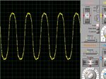
I cant able to find in which place causing the problem. For your info how i designed is from microcontroller the output is given to tc427 from tc427 the outputs are given to corresponding pins of IC IR2110.From the ir2110 the signals are applied to mosfet gates. I checked signals in oscilloscope everything is good..but why my output is always low not getting more than 200W . Second problem is at 100w i am seeing nice sine wave in oscilloscope but for 200W it turns to triangular like waveform. the output filter capacitor i used is 2.2uf/400v..

Help me to solve these problems and suggest me idea

Thank you,
 
Last edited by a moderator:

Hi,

What about showing us your schematic?
Or a scope picture of output voltage waveform, and MOSFET current.

Klaus
 

To have 800W from a 12V source, your design must pull 67A (say 80A to make up for losses). Therefore total resistance in the primary loop cannot be greater than 1/7 ohm. You need to make sure that parasitic resistance is low enough, to allow that many Amperes to go through the current loop.

Parasitic resistance can be in the battery, or transformer, or mosfets.

It should be possible to make safe tests, although you must be aware what you're doing. High voltage spikes can come from the transformer when you switch it off suddenly.
Also run tests at different switching frequencies. Etc.
 

Hi KlauSST thanks for the reply.i will post the scope picture soon

- - - Updated - - -

Hi BradtheRad thanks...I am not using a lengthy wire from my battery to the circuit. And that wire has having enough capability to draw said current like having in commercial inverters.if I applied a square wave form the pic instead of spwm signals I am getting more than 500W output. But why not with spwm ? paralleling mosfets will solve the problem ? if paralleling why I am not getting above 200W from this circuit.

- - - Updated - - -

Hi ,

I have attached the scope pictures here ..Please check these pictures 1.jpg2.jpg3.jpg4.jpg

- - - Updated - - -

The first picture Vrms 211v is with 25w load 2nd pic with additional 100W incandescent bulb load 3rd pic with one more 100W bulb For inductive load also getting the same waveform. The spike at the top edge is waveform distorted its because of 2 unmatching mosfets .When testing two mosfets were damaged at the low side. So I changed that two with other mosfets . I have with me. But previously I saw a nice sine wave with no spikes . but this is not the issue..problem is load increases output voltage decreases.for 211V at 25W load the Bat volt is 12.46V and for 125W load Bat volt is 12.00V and for 225W load the Bat Volt is 11.80V

- - - Updated - - -

Hi,
Will you please explain about these factors " Parasitic resistance can be in the battery, or transformer, or mosfets."
 

Hi,

The flat top of your sine maybe is because if saturating core. Could you check on this?

You say you changed MOSFETs, maybe they are slower. Can this cause a DC component in the primary signal?
Or cross conduction?

***
Do you have a output voltage regulation?
You may need this. For thus you have to measure output voltage and adjust (multiply) PWM value.

***
You need big, but more important low ESR bulk capacitors at the 12V side. They need to be specified fir your switching frequency and current ripple.

Klaus
 

Hi,
Will you please explain about these factors " Parasitic resistance can be in the battery, or transformer, or mosfets."

For the Amperes you need, any excess resistance is parasitic. You need to minimize resistance in all ways you can.

Make wiring contacts clean and shiny. Put a meter across them to see how much voltage they are dropping.

Did you check DC resistance through your transformer primary?

Can you take readings across your mosfets during operation?

for 211V at 25W load the Bat volt is 12.46V

and for 125W load Bat volt is 12.00V

and for 225W load the Bat Volt is 11.80V

These could be called typical readings, although this battery will have trouble supplying 800W. A healthy battery freshly charged ought to read a few tenths of a volt higher. I believe you need a larger capacity battery, or a second battery in parallel.
 

Hi KlausST,
Thanks for your suggestions I will make a change and post about the problem is solved or not

- - - Updated - - -

Hi BradtheRad,
Yes i am using a short wire from battery to the inverter circuit and wires are clean and i did not checked Dc resistance at the primary.
Yes the readings are noted in operation.

Across mosfets i am getting 12V. And how many mosfets needed or paralleled for Full bridge to get 800W ,How do i calculate the required amount of power? So that i can add mosfets for 800w

Thanks
 

As KlausST suggested i implemented feedback i see some improvement. Anyone help me to calculate how many mosfets needed for Full bridge to get 800w ?

- - - Updated - - -

Hi andre_teprom,
Yes switching frequency is 16Khz and size is a Bulky iron type transformer 12-0-12V/230V 800W Transformer. But i used only (0-12V) winding.
 

I believe that the amount of switching devices would not affect the waveform this way, seeming to be much more related to the reactive devices ( eg. output capacitor ) or even the core likely undersized.

switching frequency is 16Khz and size is a Bulky iron type transformer 12-0-12V/230V 800W Transformer. But i used only (0-12V) winding.

Are you referring to the powdered soft iron type ?
Ok, but how bulky ? One of the most significant factors that will dictate the ability of the core to drive this power is defined by its size. Can you measure the cross-section of the transformer ?
 

Hi andre_teprom ,
So you are saying the problem is not from the circuit side it may be from transformer ? The cross-section of my transformer is 3150milimetre square. My transformer looks similar to this 1.JPG

How much bulky ? It weights 7kg . In the output across I connected non polarity 2.2uf /400v cap . After u asked a cross section area I calculated for how much output power it can deliver .
I got 530W from calculation. But I am not getting more than 200W output

Thanks
 
Last edited:

The Picture above is from a laminated core, which is not suited to work with higher switching frequencies like 16KHz, due to the significant losses expected. I presume that the transformer is saturating, potentially after certain level of heating.

You can make a simple test, just working at half of its full power rating for about 10min, which is time enough to rise the temperature of the core up to a steady value. This way you can feel how much of power is lost at the transformer.
 

Apparently the circuit uses a pwm H-bridge to generate 50 Hz/8V primary voltage.
Means there's only little 16 kHz ripple in the transformer core, it doesn't generate much additional losses.

Core saturation, if happing at all would be a matter of 50 Hz and DC magnetisation.
 

So you are saying the problem is not from the circuit side it may be from transformer ?

We have to check all possibilities; as FvM remarked, we can probably eliminate the frequency as being the main reason, but I still think that the transformer could be saturating. The distorted shape gives an indication of that.

What are the ratio of the winding output (Volt/turn) ?
 

@FvM ,Yes you are right

Hi andre_teprom ,
I told clearly the distorted wave is because of unmatching mosfets. The only problem is voltage reduces from 230V to 180V at 125W load . If same battery is the problem it should not work with other inverter.i have another inverter which is a square wave type it works well till 500W.

And I bought transformer from shop they are branded in manufacturing transformers. So I don't know the turn ratios

Screenshot from simulation
 

Attachments

  • 2.JPG
    2.JPG
    56.7 KB · Views: 70
Last edited:

Thanks to Everyone who tried to help me and for the suggestions . I found the problem causing voltage to go lower. The problem is not from the transformer :) . Its working now I got output :)

Again Thanks,
 

Status
Not open for further replies.

Part and Inventory Search

Welcome to EDABoard.com

Sponsor

Back
Top