Vermes
Advanced Member level 4
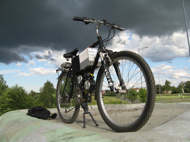
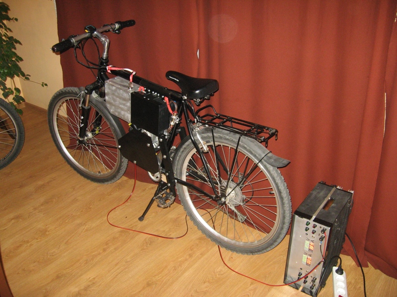
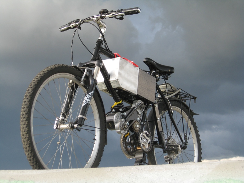
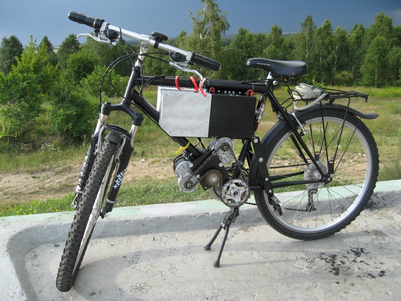
This electric vehicle was based on a bike. The design is based on a steel bike frame, properly adapted to mount the necessary components. Drive consists of two DC motors with a rated voltage of 24V connected in parallel with total power of 700W. Two AGM accumulators 20Ah each, connected in series are used to power the device. Speed control is implemented on a pulse inverter which decreases-increases voltage. The inverter is also equipped with advanced automatic features and a number of protections.
Mechanical part, power transmission:
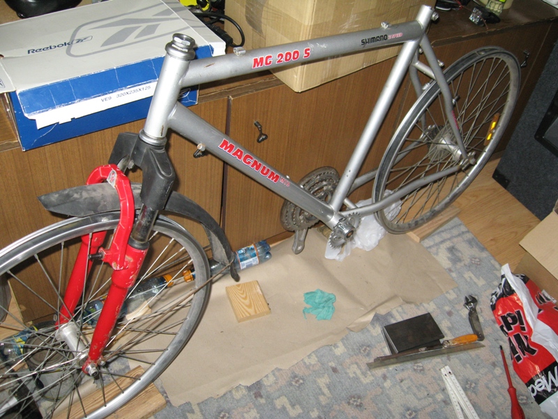
The vehicle is based on an old mountain bike frame.
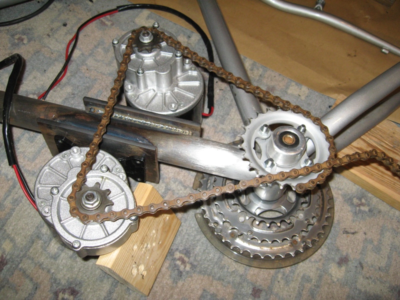
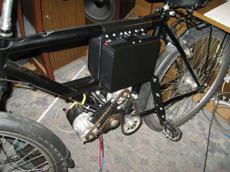
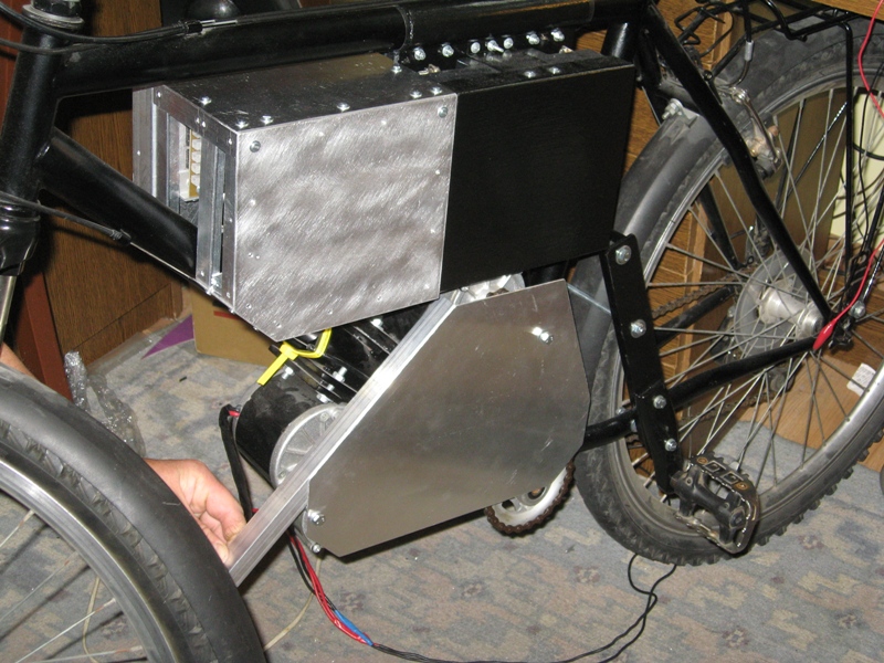
6mm thick steel sheets are soldered to the frame. Motors are screwed to those sheets. Common chain drives the left side of the crank handle, and further the torque via bottom bracket is transferred to the cogs and to the rear wheel via chain. The main advantage of this solution is that you can change gears while riding, so that the vehicle has a dynamic and can reach higher speed, despite the fact that it is a low-power device. All mechanical components should be attached very firmly. The whole is protected using black matt varnish. Tensioner between the motors reduces chain vibration during operation and allows adjustment of its play. It is made of freewheel and has inside a machine bearing. All the elements are arranged as down as possible to lower the center of gravity of the vehicle. But you still feel the weight of the vehicle during driving. Transmission prevents from turning the pedals during driving, so they were removed. Stands for legs were screwed to the frame at an angle, so there is the greatest pressure. Mounting was made of 3mm steel sheet screwed with 20x20mm channel bar using 6mm screws and 10mm spacers. A piece of the crank with the pedal is additionally bolted.
Supply:
Electric drive is supplied by two accumulators in AGM technology with a capacity of 20Ah and 12V voltage. Current paths are made of 2x4mm2 cables to achieve the minimum loss of energy. The circuit is protected by a 50A fuse used in car audio. It cannot work because automation reduces current to a value of 40A and does not exceed it. The system is also equipped with monitoring and control element, which indicates low level of accumulators voltage by flashing LED. The LED starts flashing when the voltage on accumulators drops below 22V. However, below 21,5V coupling voltage reduces the current so that the voltage does not drop below the value (the vehicle suddenly wears off – you must charge the accumulators). In the exterme case, if the coupling does not work, the whole system shuts down below 21V, with the hysteresis value of 1V, making it impossible to start the engine without recharging.
Electronics:
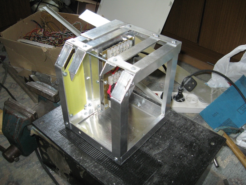
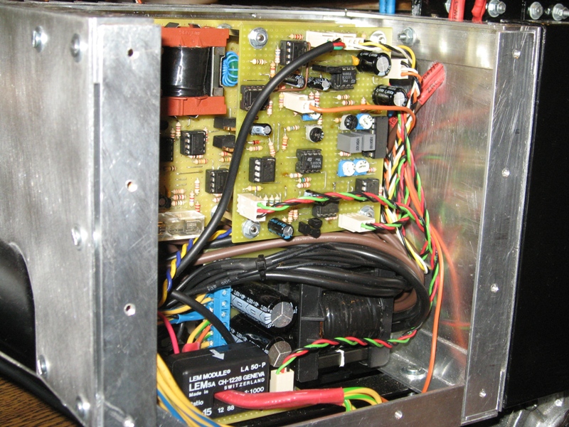
To adjust the speed of the vehicle, it is equipped with voltage regulator based on application of cascaded impulse inverters which decreases and increases the voltage and operate independently from each other. This combination allows for constant output voltage, regardless of the level of discharge of the accumulator (when the 21,5V limit appears on the accumulators, rated voltage may still be on the engines). The voltage coupling at the output provides the decent voltage regardless of the load. The vehicle has the same parameters, which are not dependent on accumulator voltage and load conditions. Current flowing in the system is dynamically limited to the maximum value of 40A (maximum current of motors according to the manufacturer's data). Measurement of current is done by a current converter from LEM. Due to the separation of the grounds, system of regulator is supplied from multi-voltage auxiliary converter with the follower feedback, which reduces the production of heat on the final line stabilizers. The device uses Hall Effect speed shifter. The housing was made of aluminum angles and 1,5mm brushed aluminum sheet.
Parameters:
Maximum speed of the vehicle is about 47km/h (downhill) but it can achieve 40km/h on a straight road. Maximum distance of a normal drive is about 30km. When the drive is dynamic (40km/h and speed shifter on the maximum position all the time), it drops to 15km. This is due to the losses of energy on inner resistance of the accumulators – the greater current taken from accumulator, the smaller its capacity.
The vehicle weighs 43kgs.
Link to original thread - Pojazd elektryczny na bazie roweru - SPEEDEE