Patrick Yang
Junior Member level 1
Hi all,
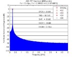
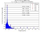
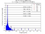
I am now designing a 14bit SAR ADC, at present, I have designed a prototype with ideal comp and sh. I run transient analysis with stop time 1s (10kS/s sampling rate), around 10000 samples, then I perform FFT analysis in MATLAB with window functions like hanning. However, large spectrum leakage appears and results vary with different window functions. The FFT code is shown in below. And its analysis result is attached using hanning, hamming and blackman window function. Can anyone tell the where the problem occurs and how to fix it? Thank U in advance.


I am now designing a 14bit SAR ADC, at present, I have designed a prototype with ideal comp and sh. I run transient analysis with stop time 1s (10kS/s sampling rate), around 10000 samples, then I perform FFT analysis in MATLAB with window functions like hanning. However, large spectrum leakage appears and results vary with different window functions. The FFT code is shown in below. And its analysis result is attached using hanning, hamming and blackman window function. Can anyone tell the where the problem occurs and how to fix it? Thank U in advance.
Code:
%***********************************************************************%
% Normalize input signal relative to full-scale
%***********************************************************************%
fin_dB=20*log10((max_code-min_code)/(2^numbit));


%***********************************************************************%
% Window function
%***********************************************************************%
% If no window function is used, the input tone must be chosen to be unique and with
% regard to the sampling frequency. To achieve this prime numbers are introduced and the
% input tone is determined by Fin = Fsample * (Prime Number / Data Record Size).
% To relax this requirement, window functions such as HANNING and HAMING (see below) can
% be introduced, however the fundamental in the resulting FFT spectrum appears 'sharper'
%without the use of window functions.
Dout=code';
Doutw=Dout;
Doutw=Dout.*hanning(numpt);
Doutw=Dout.*hamming(numpt);
Doutw=Dout.*blackman(numpt);


%***********************************************************************%
% Performing the Fast Fourier Transform [FFT]
%***********************************************************************%
span=0; %Span of the input frequency on each side; span=max(round(numpt/200),5);
spanh=0; %Approximate search span for harmonics on each side
spandc=0; %Approximate search span for DC on right side
Dout_spect=fft(Doutw);
Dout_dB=20*log10(abs(Dout_spect)); %Recalculate to dB abs(Dout_spect)
spectP=(abs(Dout_spect)).*(abs(Dout_spect)); %Determine power spectrum
maxdB=max(Dout_dB(1+spandc:numpt/2));
fin=find(Dout_dB(1:numpt/2)==maxdB); %Find the signal bin number, DC=bin1


%***********************************************************************%
% Calculate SNR, SNDR, THD and SFDR values.
%***********************************************************************%
fw=fopen(spectP_file,'w'); %write the power soectrum to file
fprintf(fw,'%12.9e\n',spectP);
fclose('all');
%Find DC offset power
Pdc=sum(spectP(1:span));
%Extract overall signal power
idx1=fin-span;
idx2=fin+span;
if(idx1<=0)
    idx1 = 1;
end
Ps=sum(spectP(idx1:idx2));
%Vector/matrix to store both frequency and power of signal and harmonics
Fh=[];
%The 1st element in the vector/matrix represents the signal, the next element represents the 2nd harmonic
Ph=[];
%Vector/matrix to store the sampling points responding to the harmonics
Nh=[];
%Ah represents signal and harmonic amplitude
Ah=[];
%Find harmonic frequencies and power components in the FFT spectrum
%For this procedure to work, ensure the folded back high order harmonics do not overlap
%with DC or signal or lower order harmonics , so it should be modified according to the actual condition
for har_num=1:5
    tone=rem((har_num*(fin-1)+1)/numpt,1); %Input tones greater than fSAMPLE are aliased back into the spectrum
    if tone>0.5
        tone=1-tone; %Input tones greater than 0.5*Fsample (after aliasing) are reflected
    end
    Fh=[Fh tone];
    %Check Nh to see the bin of the harmonics
    Nh=[Nh round(tone*numpt)];
    %For this procedure to work, ensure the folded back high order harmonics do not overlap
    %with DC or signal or lower order harmonics
    har_peak=max(spectP(round(tone*numpt)-spanh:round(tone*numpt)+spanh));
    har_bin=find(spectP(round(tone*numpt)-spanh:round(tone*numpt)+spanh)==har_peak);
    har_bin=har_bin+round(tone*numpt)-spanh-1;
    Ph=[Ph sum(spectP(har_bin-spanh:har_bin+spanh))];
    Ah=[Ah Dout_dB(har_bin)];
end
%Determine the total distortion power, it should be modified according to the actual condition.
Pd=sum(Ph(2:5));
%Determine the noise power
Pn=sum(spectP(1:numpt/2))-Pdc-Ps-Pd;
%Determine the next largest component
spur_max=max(max(spectP(spandc+1:fin-span-1)),max(spectP(fin+span+1:numpt/2)));
spur_bin=find(spectP(1:numpt/2)==spur_max)
%**********************Dynamic specs**********************%
format; %
SFDR = 10*log10(max(spectP(1:numpt/2))/spur_max); %-fin_dB
THD = 10*log10(Pd/Ps); %+fin_dB
SNR = 10*log10(Ps/Pn); %-fin_dB
SNDR = 10*log10(Ps/(Pn+Pd)); %-fin_dB
ENOB = (SNDR-1.76)/6.02;
%disp('Note: THD is calculated from 2nd through 10th order harmonics.');
%*********************Signal and its harmonics*********************%
%hold on;
%plot((Nh(2:10)-1).*fres,Ah(2:10)-maxdB+fin_dB,'rs');
% Signal
bins=(Nh(1)-1)*fres;
Ahs=Ah(1)-maxdB+fin_dB;
% 2nd harmonic
bin2=(Nh(2)-1)*fres;
Ah2=Ah(2)-maxdB+fin_dB;
% 3rd harmonic
bin3=(Nh(3)-1)*fres;
Ah3=Ah(3)-maxdB+fin_dB;
% 4th harmonic
bin4=(Nh(4)-1)*fres;
Ah4=Ah(4)-maxdB+fin_dB;
% 5th harmonic
bin5=(Nh(5)-1)*fres;
Ah5=Ah(5)-maxdB+fin_dB;


