Continue to Site

Welcome to EDAboard.com

Welcome to our site! EDAboard.com is an international Electronics Discussion Forum focused on EDA software, circuits, schematics, books, theory, papers, asic, pld, 8051, DSP, Network, RF, Analog Design, PCB, Service Manuals... and a whole lot more! To participate you need to register. Registration is free. Click here to register now.

[PIC] Software PWM using PIC12F/16FXX Timer1 and Timer0.

Status
Not open for further replies.

johnnyprimavera

Newbie level 4
Joined
Mar 21, 2013
Messages
6
Helped
1
Reputation
2
Reaction score
1
Trophy points
1,283
Activity points
1,382
Hello everyone.

I'm using a PIC12F629 (PIC10F200 or PIC12F675 should also work) and I'd like to implement Pulse Width Modulation using Timer1 and Timer0 and the internal clock at 8Mhz. I'm aware that, for example, PIC12F683 has hard PWM CCP module built in, but for backward compatibility in my design and other reasons I'll have soft PWM.

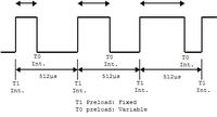
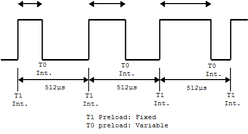
16-bit Timer1 generates the PWM frequency, e.g. 1953.13Hz (period of 512µs). At every Timer1 interrupt the signal on the output pin (GPIO.4) will be set HIGH.

8-bit Timer0 is responsible to clear the ouput to LOW after "some amount of time" has passed, before the next Timer1 interrupt occurs. Therefore changing this amount of time (fraction of 2^8bits = 256) will give different duty cycles for the signal on the output. That's it: 8-bit PWM.

Here's the code (MikroBasic 6.0 Compiler).


Code Basic4GL - [expand]
1
2
3
4
5
6
7
8
9
10
11
12
13
14
15
16
17
18
19
20
21
22
23
24
25
26
27
28
29
30
31
32
33
34
35
36
37
38
39
40
41
42
43
44
45
46
47
48
program Candle_NOT_PWM
Dim pink as byte
 
sub procedure InitTimer()
  T1CON = 0x01           'Sets Timer1 Prescaler @ 1:1
  OPTION_REG = 0x81   'Sets Timer0 Prescaler @ 1:4
  
  PIR1.TMR1IF = 0        'Resets TMR1
  
  TMR1H = 0xFC           'Preloads TMR1 value: 64512; generates 0.512ms timer.
  TMR1L = 0x00
  TMR0 = 0
  
  PIE1.TMR1IE = 1        'Activates TMR1
  INTCON.T0IE = 1        'Activates TMR0
  INTCON = 0xC0          'Sets GIE and PEIE.
end sub
 
sub procedure Interrupt()
  if (PIR1.TMR1IF) then
    PIR1.TMR1IF = 0      'Resets TMR1
    TMR1H = 0xFC
    TMR1L = 0x00
    TMR0 = 255 - pink    'Pink is the variable (0 to 255) that controls duty cycle of PWM.
    INTCON.T0IE = 1      'Activates TMR0
    GPIO.4 = 1              'Output is HIGH
  end if
  
  if (INTCON.T0IF) then
     INTCON.T0IF = 0   'Resets TMR0
     GPIO.4 = 0           'Output is LOW
  end if
end sub
 
main:
CMCON = 0x07           'All pins configured as Digital I/O
TRISIO = %001000      'Only GPIO.3 is input.
GPIO = %000000         'Clears all outputs.
InitTimer()
 
while(TRUE)
  'Performs a linear increase of duty cycle to test its function.
  '  for pink = 0 to 255
  '  delay_ms(100)
  '  next pink
   pink = 128              'Fixed value on pink.
wend
end.


The problem I have is related to timing issues.

1. I measured with a PC Oscilloscope the time between two successive TMR1 interrupts and it's 990µs, when it should be 512µs.

2. Setting the pink variable (PWM duty cycle from 0 to 255) to 128 should give a HIGH period of half the TMR1 period(512µs / 2 = 256µs), but it's measured as 500µs and a measured DC of 51.0%.

3. The PWM signal works from 3.1% measured to 97.0% measured. Higher or lower than this, the signal is always LOW.

I've read that there's the Interrupt latency which may add 3 clock cycles (500ns each), and after loading the timer registers, they will took up 2 more cycles to syncronise. And the lines of code in my ISR also affect. Does all those timing problems arose from the latter? I'd appreciate a 0% to 100% controllable PWM signal, in 0.39% steps (100/256). As for the PWM frequency, the higher the better.

Thanks, and I hope it's not too much!
John
 

1. the 12F629 has an internal clock at 4MHz not 8MHz, that's why it seems to run at half speed!

I would guess you are correct about the remaining error being due to latency. Some will be due to the hardware and some to the code added by the compiler. When I have to work with 'precision' PWM in this kind of device I always write in assembly language to minimize the latter.

Brian.
 
Thanks Brian, of course, the 4MHz internal clock. I can't understand know how I've overseen it.

But have you got any more insight about how to compensate those offsets? Something like counting the assembly instructions and clock cycles. I've checked that:


Duty | measured
Cycle* | DC*
------------------
25 40
35 49
45 58
55 68
65 78
85 96
105 115
------------------
*(over 255)

Numbers are yelling at me: it gives a lineal relationship of

expected DC = 0.9461 * measured + 15.955

That's an offset of 16 µs when running @4Mhz and T1 (period between two consecutive TMR1 interrupts) being 256µs.

1. Having the ASM file the compiler generates, how can I count and correct those offsets?


Code ASM - [expand]
1
2
3
4
5
6
7
8
9
10
11
12
13
14
15
16
17
18
19
20
21
22
23
24
25
26
27
28
29
30
31
32
33
34
35
36
37
38
39
40
41
42
43
44
45
46
47
48
49
50
51
52
53
54
55
56
57
58
59
60
61
62
63
64
65
66
67
68
69
70
71
72
73
74
75
76
77
78
79
80
81
82
83
84
85
86
87
88
89
90
91
92
93
94
95
96
97
98
99
100
101
102
103
104
105
106
107
_InitTimer:
 
;Candle_NOT_PWM.mbas,4 ::               sub procedure InitTimer()
;Candle_NOT_PWM.mbas,5 ::               T1CON = 0x01           'Sets Timer1 Prescaler @ 1:1
        MOVLW      1
        MOVWF      T1CON+0
;Candle_NOT_PWM.mbas,6 ::               OPTION_REG = 0x88      'Sets Timer0 Prescaler @ 1:1
        MOVLW      136
        MOVWF      OPTION_REG+0
;Candle_NOT_PWM.mbas,8 ::               PIR1.TMR1IF = 0        'Resets TMR1
        BCF        PIR1+0, 0
;Candle_NOT_PWM.mbas,10 ::              TMR1H = 0xFF           'Preloads TMR1 value: 65280; generates 0.256ms timer.
        MOVLW      255
        MOVWF      TMR1H+0
;Candle_NOT_PWM.mbas,11 ::              TMR1L = 0x00
        MOVLW      16
        MOVWF      TMR1L+0
;Candle_NOT_PWM.mbas,12 ::              TMR0 = 0
        CLRF       TMR0+0
;Candle_NOT_PWM.mbas,14 ::              PIE1.TMR1IE = 1        'Activates TMR1
        BSF        PIE1+0, 0
;Candle_NOT_PWM.mbas,15 ::              INTCON.T0IE = 1        'Activates TMR0
        BSF        INTCON+0, 5
;Candle_NOT_PWM.mbas,16 ::              INTCON = 0xC0          'Sets GIE and PEIE.
        MOVLW      192
        MOVWF      INTCON+0
;Candle_NOT_PWM.mbas,17 ::              end sub
L_end_InitTimer:
        RETURN
; end of _InitTimer
 
_Interrupt:
        MOVWF      R15+0
        SWAPF      STATUS+0, 0
        CLRF       STATUS+0
        MOVWF      ___saveSTATUS+0
        MOVF       PCLATH+0, 0
        MOVWF      ___savePCLATH+0
        CLRF       PCLATH+0
 
;Candle_NOT_PWM.mbas,19 ::              sub procedure Interrupt()
;Candle_NOT_PWM.mbas,20 ::              if (PIR1.TMR1IF) then
        BTFSS      PIR1+0, 0
        GOTO       L__Interrupt3
;Candle_NOT_PWM.mbas,21 ::              PIR1.TMR1IF = 0      'Resets TMR1
        BCF        PIR1+0, 0
;Candle_NOT_PWM.mbas,22 ::              TMR1H = 0xFF
        MOVLW      255
        MOVWF      TMR1H+0
;Candle_NOT_PWM.mbas,23 ::              TMR1L = 0x00
        MOVLW      16
        MOVWF      TMR1L+0
;Candle_NOT_PWM.mbas,24 ::              TMR0 = 255 - pink + 3    'Pink is the variable (0 to 255) that controls duty cycle of PWM.
        MOVF       _pink+0, 0
        SUBLW      255
        MOVWF      R0+0
        MOVLW      3
        ADDWF      R0+0, 0
        MOVWF      TMR0+0
;Candle_NOT_PWM.mbas,25 ::              INTCON.T0IE = 1      'Activates TMR0
        BSF        INTCON+0, 5
;Candle_NOT_PWM.mbas,26 ::              GPIO.4 = 1           'Output is HIGH
        BSF        GPIO+0, 4
L__Interrupt3:
;Candle_NOT_PWM.mbas,29 ::              if (INTCON.T0IF) then
        BTFSS      INTCON+0, 2
        GOTO       L__Interrupt6
;Candle_NOT_PWM.mbas,30 ::              INTCON.T0IF = 0   'Resets TMR0
        BCF        INTCON+0, 2
;Candle_NOT_PWM.mbas,31 ::              GPIO.4 = 0        'Output is LOW
        BCF        GPIO+0, 4
L__Interrupt6:
;Candle_NOT_PWM.mbas,33 ::              end sub
L_end_Interrupt:
L__Interrupt16:
        MOVF       ___savePCLATH+0, 0
        MOVWF      PCLATH+0
        SWAPF      ___saveSTATUS+0, 0
        MOVWF      STATUS+0
        SWAPF      R15+0, 1
        SWAPF      R15+0, 0
        RETFIE
; end of _Interrupt
 
_main:
 
;Candle_NOT_PWM.mbas,35 ::              main:
;Candle_NOT_PWM.mbas,36 ::              CMCON = 0x07           'All pins configured as Digital I/O
        MOVLW      7
        MOVWF      CMCON+0
;Candle_NOT_PWM.mbas,37 ::              TRISIO = %001000       'Only GPIO.3 is input.
        MOVLW      8
        MOVWF      TRISIO+0
;Candle_NOT_PWM.mbas,38 ::              GPIO = %000000         'Clears all outputs.
        CLRF       GPIO+0
;Candle_NOT_PWM.mbas,39 ::              InitTimer()
        CALL       _InitTimer+0
;Candle_NOT_PWM.mbas,40 ::              while(TRUE)
L__main10:
;Candle_NOT_PWM.mbas,45 ::              pink = 165
        MOVLW      165
        MOVWF      _pink+0
;Candle_NOT_PWM.mbas,46 ::              wend
        GOTO       L__main10
L_end_main:
        GOTO       $+0
; end of _main


I appreciate your answers very much.
 

I realize this thread is a month old, but if I may I ask a very basic question here on your design, why are you using two timers for this process, instead of simply having a short interrupt routine on 1 timer interval that compares the desired duty cycle setting against a counter, and either pulls the output high or low based on that comparrison? It would greatly reduce your instruction cycles.
 

I think the easiest way to do this use microC pro in which there is a built in PWM library.
 

I'm using two timers to reduce CPU working time to a minimum. All is handled by Timer peripherals and the interrupts.

MikroBasic Has an in-built library for PWM, however it implies the PIC has the hard PWM module, which PIC12F629, PIC10F200 or PIC12F675 haven't.
 

I'm still not seeing how this reduces instruction cycles, because the routine itself is more cumbersome, but it might be a lesson I need to learn by stepping through a program in debug mode. I'm certainly no expert, but I've worked with PWM a lot.

I would personally try using TMR1 and reducing your PWM frequency. It would reduce both the number of calls to the subroutine, and the number of instruction cycles in the routine itself.

Here is a routine I used (in C) on a PIC12F1501 to control brightness of a display (actually an RGB control, but I removed the second and third PWM levels just to show you as an example). I used 0-99 for brightness levels just to keep it simple, but you can chose your resolution as you wish:
Code:
void ISR ()
{
if ( pwm_counter == 0 )		// checks the counter variable
	{
	PORTA=&0b00000001;	// if zero, pull output high
	}
if ( pwm_counter = duty_cycle )	// check counter against duty_cycle ( a number from 0-99 )
	{
	PORTA=^0b00000001;	// if counter equals duty_cycle, pull output low
	}
if ( pwm_counter < 99 )		// check to see if counter reached 99 yet 
	{
	pwm_counter=pwm_counter++;	// if not, increment it
	}
	else
	{
	pwm_counter=0;		// if yes, reset it
	}
}
I was using an 8 bit timer, but the PWM color control is the primary function of the IC, so I wasn't terribly concerned about CPU load. If you use the 16 bit timer, and increase the prescaler, you can reduce the calls to the cubroutine and reduce your PWM frequency, thereby reducing your CPU load.
 

Let's get it down to an assembly level:

Each IF is implemented by the compiler as either a BTFSC or BTFSS two-cycle instruction. The < operator for two bytes roughly takes 4 instruction cycles. Using an internal timer0 as counter, it increases automatically after a known amount of time, thus the code doesn't have to bother incrementing the counting variable. (that's the key point) Then I use another timer1 for PWM base frequency generation. Each time it overflows you set the input high. Each time counter = duty_cycle set the input low.

ISR:
If (interrupt due to timer 1) output HIGH -- roughly 3 instructions
If (interrupt due to timer 0) output LOW -- roughly 5 instructions
timer0 preload = duty_cycle

So you don't have to set the value for the counter and save roughly 4 instructions for the < operator and the BTFSx operation. Also, timing is easier to make more accurate. The down part: there's a trade off between output frequency and accesses to sobroutine.

Code:
void ISR ()
{
if ( pwm_counter == 0 )		// checks the counter variable                                                                      1
	{
	PORTA=&0b00000001;	// if zero, pull output high                                                                            2
	}
if ( pwm_counter = duty_cycle )	// check counter against duty_cycle ( a number from 0-99 )                             3
	{
	PORTA=^0b00000001;	// if counter equals duty_cycle, pull output low                                                2
	}
if ( pwm_counter < 99 )		// check to see if counter reached 99 yet                                                       6
	{
	pwm_counter=pwm_counter++;	// if not, increment it                                                                           1
	}
	else
	{
	pwm_counter=0;		// if yes, reset it                                                                                                  1
	}
}                                                                                                                                                          -------------
                                                                                                                                                                 16 inst. cycles.
 

OK, I see where you're going with the TMR0. I was missing the fact that you're scaling it for the duty cycle.

Now I understand how it's working, and I'm wrapping my head around the whole program.

I think it's the +3 you have in the setting of TMR0 for the duty cycle.
I think I know what the purpose is, but please explain your reasoning.


edit: I read back through the original post again, and I see that the +3 is probably there because of the latency issue you brought up. However, I think that's only part of it:

Because your timers are reset in software, they are not in sync.

I think (and I could be wrong) the only way to fix this is to rewrte your program to have the timers roll over instead of having them reset with the software. Add to this the fact that if the call to TMR1 always turns on the pin, you can not have an absolute 0% duty cycle ever, because that pin will be on every cycle even if only for a few µs. Does this make sense?

I hope this insight is helpful.
 
Last edited:

Status
Not open for further replies.

Similar threads

Part and Inventory Search

Welcome to EDABoard.com

Sponsor

Back
Top