johnnyprimavera
Newbie level 4

- Joined
- Mar 21, 2013
- Messages
- 6
- Helped
- 1
- Reputation
- 2
- Reaction score
- 1
- Trophy points
- 1,283
- Activity points
- 1,382
Hello everyone.
I'm using a PIC12F629 (PIC10F200 or PIC12F675 should also work) and I'd like to implement Pulse Width Modulation using Timer1 and Timer0 and the internal clock at 8Mhz. I'm aware that, for example, PIC12F683 has hard PWM CCP module built in, but for backward compatibility in my design and other reasons I'll have soft PWM.
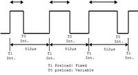
16-bit Timer1 generates the PWM frequency, e.g. 1953.13Hz (period of 512µs). At every Timer1 interrupt the signal on the output pin (GPIO.4) will be set HIGH.
8-bit Timer0 is responsible to clear the ouput to LOW after "some amount of time" has passed, before the next Timer1 interrupt occurs. Therefore changing this amount of time (fraction of 2^8bits = 256) will give different duty cycles for the signal on the output. That's it: 8-bit PWM.
Here's the code (MikroBasic 6.0 Compiler).

The problem I have is related to timing issues.
1. I measured with a PC Oscilloscope the time between two successive TMR1 interrupts and it's 990µs, when it should be 512µs.
2. Setting the pink variable (PWM duty cycle from 0 to 255) to 128 should give a HIGH period of half the TMR1 period(512µs / 2 = 256µs), but it's measured as 500µs and a measured DC of 51.0%.
3. The PWM signal works from 3.1% measured to 97.0% measured. Higher or lower than this, the signal is always LOW.
I've read that there's the Interrupt latency which may add 3 clock cycles (500ns each), and after loading the timer registers, they will took up 2 more cycles to syncronise. And the lines of code in my ISR also affect. Does all those timing problems arose from the latter? I'd appreciate a 0% to 100% controllable PWM signal, in 0.39% steps (100/256). As for the PWM frequency, the higher the better.
Thanks, and I hope it's not too much!
John
I'm using a PIC12F629 (PIC10F200 or PIC12F675 should also work) and I'd like to implement Pulse Width Modulation using Timer1 and Timer0 and the internal clock at 8Mhz. I'm aware that, for example, PIC12F683 has hard PWM CCP module built in, but for backward compatibility in my design and other reasons I'll have soft PWM.
16-bit Timer1 generates the PWM frequency, e.g. 1953.13Hz (period of 512µs). At every Timer1 interrupt the signal on the output pin (GPIO.4) will be set HIGH.
8-bit Timer0 is responsible to clear the ouput to LOW after "some amount of time" has passed, before the next Timer1 interrupt occurs. Therefore changing this amount of time (fraction of 2^8bits = 256) will give different duty cycles for the signal on the output. That's it: 8-bit PWM.
Here's the code (MikroBasic 6.0 Compiler).
Code Basic4GL - [expand]

The problem I have is related to timing issues.
1. I measured with a PC Oscilloscope the time between two successive TMR1 interrupts and it's 990µs, when it should be 512µs.
2. Setting the pink variable (PWM duty cycle from 0 to 255) to 128 should give a HIGH period of half the TMR1 period(512µs / 2 = 256µs), but it's measured as 500µs and a measured DC of 51.0%.
3. The PWM signal works from 3.1% measured to 97.0% measured. Higher or lower than this, the signal is always LOW.
I've read that there's the Interrupt latency which may add 3 clock cycles (500ns each), and after loading the timer registers, they will took up 2 more cycles to syncronise. And the lines of code in my ISR also affect. Does all those timing problems arose from the latter? I'd appreciate a 0% to 100% controllable PWM signal, in 0.39% steps (100/256). As for the PWM frequency, the higher the better.
Thanks, and I hope it's not too much!
John


