Continue to Site

Welcome to EDAboard.com

Welcome to our site! EDAboard.com is an international Electronics Discussion Forum focused on EDA software, circuits, schematics, books, theory, papers, asic, pld, 8051, DSP, Network, RF, Analog Design, PCB, Service Manuals... and a whole lot more! To participate you need to register. Registration is free. Click here to register now.

Single Rail op-amp to detect current

Status
Not open for further replies.

JazzRei

Member level 1
Joined
Oct 13, 2010
Messages
33
Helped
0
Reputation
0
Reaction score
0
Trophy points
1,286
Activity points
1,499
Hi,

I need help with my design of single rail op-amp to detect current.
With input range of 1V to 12V into the op-amp to detect current not exceeding 3V.
As I know that I require higher voltage than 12V to power up the op-amp if the input to the op-amp is 12V. How am I able to operate the op-amp?
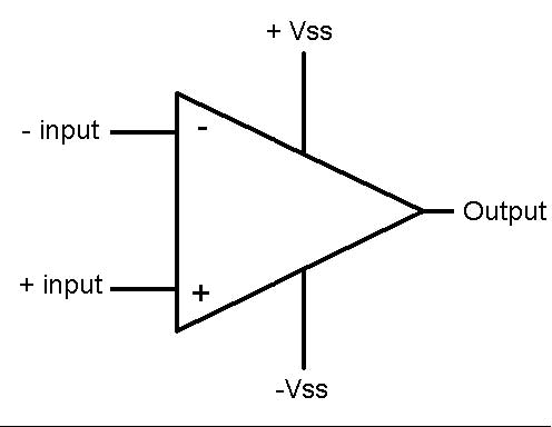
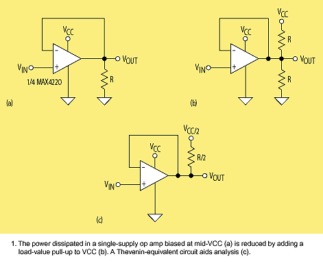
62_1295248162.jpg

43_1295248162.gif
 

Hi sorry.. I mean I m designing current not exceeding 3A...
 

Hi,

Using an op-amp, with the above diagram, is it possible to turn the op-amp on and measure the current which Vcc must be greater than Vin? How do I make Vcc greater than Vin if my maximum Vin is 12V else my op-amp cant operate. I need a single rail op-amp since I got a ositive output. Can anyone give me advice on that?

Thanks.
 

You can use a potential divider to tailer the input voltage to any level you like!

Attached is a typical current sensing circuit.
Adjust R5 and R4 to get your input range.
Adjust R2 and R3 to adjust op amp gain. Gain = (R2 + R3) / R3.
 

Attachments

  • Current_Amp.pdf
    8.8 KB · Views: 111

Hi btbass,

U measure the current at the input? What is the output for? What is the R26 and R1?
 

You have already posted the solution in your previous thread. I don't understand, why you are starting a new discussion instead of simply calculating the given circuit and see, how it performs. There is no better one.

https://www.edaboard.com/threads/198299/#post834164
 
Hi FvM,

The circuit can't work. If the power supply is 12V, then how much power I need to power up the op-amp? It must be greater than 12V. I can't use external power supply. How do I power my op-amp then?
It will not work if I use 5V to power op-amp and with power supply of 12V.
 
Last edited:

R26 is the current sense resistor. R1 is a filter for the output voltage which goes to your A/D input, so you can measure the output voltage which is related to current.
This is low side current measuring, if you want Hi side, use a ZXCT1081 IC.
 

The circuit can't work.
Of course it can.
If the power supply is 12V, then how much power I need to power up the op-amp?
You didn't manage to make a clear statement about your intended power supply. In this thread, you even didn't say, if you intend a high side measurement. Actually, the input voltage can be higher than the OP supply, because the voltage divider reduces the voltage at the OP input .
It will not work if I use 5V to power op-amp and with power supply of 12V.
With a respective resistor ratio, it's possible, but not reasonable, because the measurement gets inaccurate. Why can't you supply an OP with the DC input voltage?
Using a special high side sense amplifier is the opther option.
 

Status
Not open for further replies.

Part and Inventory Search

Welcome to EDABoard.com

Sponsor

Back
Top