wfg42438
Member level 3
- Joined
- Jun 29, 2015
- Messages
- 54
- Helped
- 0
- Reputation
- 0
- Reaction score
- 0
- Trophy points
- 6
- Location
- California
- Activity points
- 620
Hello,
Below are plots for two idealized single phase converters where the source inductance is 0
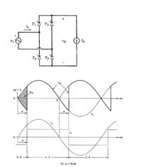
Case 1 the converter has a sinusoidal input applied to 4 thyristors and with a DC current source as a load
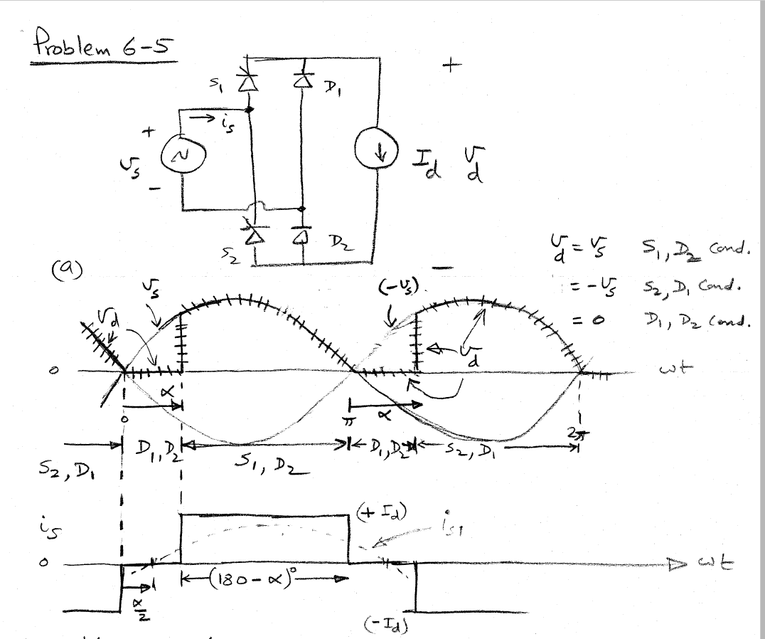
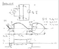
Case 2 the converter has a sinusoidal input applied to 2 thyristors, 2 diodes and with a DC current source as a load
Now based on the text i know thyristors require a pulse applied to its gate terminal in order to begin conduction
The time at which this current is applied is what we call "alpha"
For Case 1 before wt=alpha we have a negative voltage building up, can someone please explain what is happening for this to occur??
When looking at Case 2 the negative voltage we observed earlier prior to wt=alpha is no longer the case. We simply have a positive voltage produced after alpha, why has this changed in case 2?
Any insight and help would be greatly appreciated!!!
Below are plots for two idealized single phase converters where the source inductance is 0
Case 1 the converter has a sinusoidal input applied to 4 thyristors and with a DC current source as a load
Case 2 the converter has a sinusoidal input applied to 2 thyristors, 2 diodes and with a DC current source as a load
Now based on the text i know thyristors require a pulse applied to its gate terminal in order to begin conduction
The time at which this current is applied is what we call "alpha"
For Case 1 before wt=alpha we have a negative voltage building up, can someone please explain what is happening for this to occur??
When looking at Case 2 the negative voltage we observed earlier prior to wt=alpha is no longer the case. We simply have a positive voltage produced after alpha, why has this changed in case 2?
Any insight and help would be greatly appreciated!!!