Continue to Site

Welcome to EDAboard.com

Welcome to our site! EDAboard.com is an international Electronics Discussion Forum focused on EDA software, circuits, schematics, books, theory, papers, asic, pld, 8051, DSP, Network, RF, Analog Design, PCB, Service Manuals... and a whole lot more! To participate you need to register. Registration is free. Click here to register now.

Sinewave inverter prototype...

Status
Not open for further replies.
Dear deepone/naseerak
Sir
Can u send complete final schematic without any error and source code with all details which i can make and test
 

Hi, Engmunir. You may try circuit with atmega8 mcu from message #88.

________________________
Why such a wide range 10-----24v supply, transformer also has to be changed.
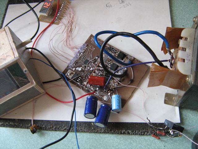
this because i will test output voltage regulation without changing sine tables.
________________________
apropos, last circuit with attiny13 is not work (
 
Last edited:

Dear Deepone
which source code is used for msg #88 circuit. detail??
 

test version of previously announced STM8S-based converter )
 

Attachments

  • c&hex.zip
    7.1 KB · Views: 131

Hi DeepOne and sorry for going off-topic. I am talking about one of smps circuit you posted earlier, plz tell me the size of the Core for this power I have EE42 (gaped) EE40, EE55 can I use these for charging 48V battries (12V in series) with current of 15A-20A.
Thanks and regards.
 

Attachments

  • 2830563200_1357207941.gif
    2830563200_1357207941.gif
    154.5 KB · Views: 257

Hi Naseerak. You may use some program for core calculations, like ExcellentIT.


but this old scheme is not very good, in gdt driving and short circuit protection parts
 
Last edited by a moderator:

corrected version of tiny13 converter (only spwm for testing purpose, but it work).
 

Attachments

  • c&hex.zip
    1.8 KB · Views: 177

DC output converter project, but similar with previous in schematics and with HF transformer instead of steel core transformer. For power tools with collector motor.
 

Attachments

  • c&hex.zip
    2.2 KB · Views: 125

Next version of last tiny13 converter for power tools.

And next sinewave inverter prototype project )
 

Attachments

  • t13_c&hex.zip
    2.2 KB · Views: 151

Hello DeepOne. I want to collect the UPS on the principle of double conversion (on-line). But when I began to search the internet approximate circuit solution proved that the presence of only the block diagram and description of the work. You ready to DC / AC with a sine wave output. If you add the PFC and charger will UPS on-line. I wonder such a device to collect for a gas boiler.
 

Hello, Algri.
I think easiest way to obtain on-line UPS is in combine PC ATX PSU, any step-up 5V to 13,6V converter with current stabilizer and the DC/AC stage converter.
 

The idea of online UPS based ATX PSU thought out is not difficult but I want to unload the 12 volt batteries ispolzova 24 volts. And I think to be right in terms of circuitry to build a block diagram.
1.JPG
PFC want to use the UC3854 sama getting the best efficiency. PFC will operate in the range of stresses 165 - 265 volts. Giving the output constant 400 volts. Thereby obtaining stabilization
UC38541-1024x660.gif
 

test version of spwm converter with ferrite transformer. not very good output signal, but it work.
 

Attachments

  • c&hex.zip
    2.4 KB · Views: 104
Last edited:

Corrected wave distortions - they were by reason of used very slow IGBT as upper bridge keys. With all IRF740 keys waveforms is ok.
 

Attachments

  • pcb.rar
    18.5 KB · Views: 149

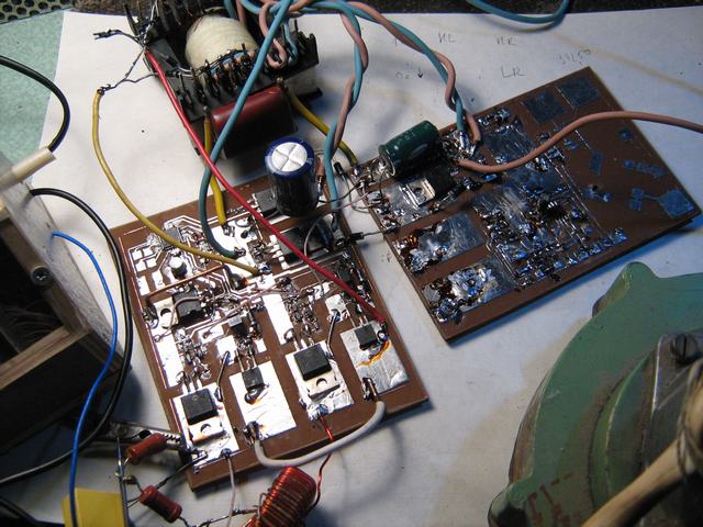
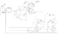
slightly modified, with additional drivers on push-pull keys
 

Attachments

  • c hex pcb.rar
    24.9 KB · Views: 141

that is experimental version, not very powerful - i think no more than 150W. but power is not a big problem. at 50W output all semiconductors are cold )
 

Status
Not open for further replies.

Part and Inventory Search

Welcome to EDABoard.com

Sponsor

Back
Top